|
5.3 Constrained Feedback Stabilization
In many applications, it may not be enough to stabilize the system. The user should be able to place the eigenvalues in a certain stability region according to prescribed design constraints, such as the lower bound for minimal damping ratio, minimal damping factor (decay rate), settling time, minimal (undamped) natural frequency, and so on. This gives rise to the constrained feedback stabilization problem that is concerned with placing the eigenvalues in a user-specified region of the complex plane using feedback. The four regions available in Advanced Numerical Methods are: DampingFactorRegion[ ], SettlingTimeRegion[ ], SettlingTimeRegion[ , ,  ], DampingRatioRegion[ ], DampingRatioRegion[ ], and NaturalFrequencyRegion[ ], and NaturalFrequencyRegion[ ]. These regions for the continuous-time system are defined in the following discussion. For the discrete-time system, the transformation ]. These regions for the continuous-time system are defined in the following discussion. For the discrete-time system, the transformation  ( ( is the sampling period of the system) maps a continuous-time stability region to the corresponding discrete-time stability region. is the sampling period of the system) maps a continuous-time stability region to the corresponding discrete-time stability region.
Consider a continuous-time system with a pair of closed-loop stable eigenvalues specified by  . The four user-specified regions, which could contain such paired eigenvalues, are defined in the following discussion. . The four user-specified regions, which could contain such paired eigenvalues, are defined in the following discussion.
DampingFactorRegion[ ] designates the region that consists of all ] designates the region that consists of all  such that such that  as shown in Figure 5.1. The parameter as shown in Figure 5.1. The parameter  is called the damping factor of the state-space system. is called the damping factor of the state-space system.
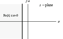
Figure 5.1. The minimal damping factor  of the continuous-time closed-loop system: the poles lie in the region of the continuous-time closed-loop system: the poles lie in the region  . .
SettlingTimeRegion[ , ,  ] denotes the region that consists of all ] denotes the region that consists of all  such that such that  as shown in Figure 5.2. The parameter as shown in Figure 5.2. The parameter  is called the settling time of the state-space system and the parameter is called the settling time of the state-space system and the parameter  species that the system response should settle within species that the system response should settle within  % of its final value. By default, if the parameter % of its final value. By default, if the parameter  is not specified, the system response is assumed to settle within 5% of its final value with is not specified, the system response is assumed to settle within 5% of its final value with  and and  . Obviously, the same region on the complex plane can be defined using either DampingFactorRegion or SettlingTimeRegion. . Obviously, the same region on the complex plane can be defined using either DampingFactorRegion or SettlingTimeRegion.
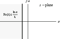
Figure 5.2. The maximal settling time  of the continuous-time closed-loop system: the poles lie in the region of the continuous-time closed-loop system: the poles lie in the region  . .
DampingRatioRegion[ ] designates the region that consists of all ] designates the region that consists of all  such that such that  and and  as shown in Figure 5.3. The parameter as shown in Figure 5.3. The parameter  is called the damping ratio of the state-space system. is called the damping ratio of the state-space system.
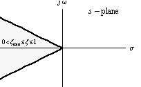
Figure 5.3. The minimum damping ratio  of the continuous-time closed-loop system: the poles lie in the region of the continuous-time closed-loop system: the poles lie in the region  . .
NaturalFrequencyRegion[ ] specifies the region that consists of all ] specifies the region that consists of all  such that such that  and and  as shown in Figure 5.4. The parameter as shown in Figure 5.4. The parameter  is called the (undamped) natural frequency of the state-space system. is called the (undamped) natural frequency of the state-space system.
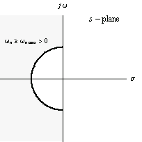
Figure 5.4. The minimum (undamped) natural frequency  of the continuous-time closed-loop system: the poles lie in the region of the continuous-time closed-loop system: the poles lie in the region  . .
As mentioned, the defined stability regions for the continuous-time systems have their discrete-time counterparts. In general, the discrete-time stability region is the image of the complex transformation  applied to the corresponding continuous-time stability region. For example, the continuous-time stability region depicted in Figure 5.2 is transformed to the following discrete-time stability region. applied to the corresponding continuous-time stability region. For example, the continuous-time stability region depicted in Figure 5.2 is transformed to the following discrete-time stability region.
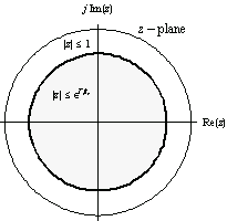
Figure 5.5. The maximal settling time  of the discrete-time closed-loop system: the poles lie in the region of the discrete-time closed-loop system: the poles lie in the region  . .

The closed-loop system performance specifications.
The function StateFeedbackGains can be used to solve a constrained feedback stabilization problem if the list of closed-loop poles is replaced by a list of the form  or, equivalently, by an expression of the form or, equivalently, by an expression of the form  , signifying the intersection of the , signifying the intersection of the  , ,  , and so on. , and so on.


Constrained feedback stabilization.
All pole assignment methods work equally well for constrained feedback stabilization problems. Additionally, if the only constraint is either DampingFactorRegion[ ] or SettlingTimeRegion[ ] or SettlingTimeRegion[ , ,  ], then the method called Lyapunov feedback stabilization method, described in Section 5.4, can be used as an alternative. ], then the method called Lyapunov feedback stabilization method, described in Section 5.4, can be used as an alternative.
Make sure the application is loaded.
In[1]:=
Load the collection of test examples.
In[2]:=
This is a model of a drum boiler.
In[3]:=
Out[3]=
These are the open-loop poles, arranged in ascending order of their real parts.
In[4]:=
Out[4]=
The feedback gain matrix guarantees that the closed-loop system has both the damping factor less than  and the damping ratio greater than and the damping ratio greater than  . .
In[5]:=
Out[5]=
Make sure the function MultipleListPlot is available.
In[6]:=
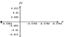
This displays the closed-loop poles of the drum boiler model on the complex plane. Both design specifications are met.
In[7]:=
Out[7]=
In[8]:=
|