|
5.1 Root Loci


Plotting the root loci.
RootLocusPlot graphs the roots of the characteristic equation (the root loci) while some parameter, typically (but not necessarily) the gain, varies. The input system may be in state-space or transfer function form and may or may not depend on the parameter k. In the latter case, the parameter is assumed to be the gain of the open-loop system. Both discrete- and continuous-time systems can be analyzed using this function. As in the Electrical Engineering Examples, RootLocusPlot (as well as BodePlot, NyquistPlot, and NicholsPlot) also accepts the body of the transfer function object as the input system.
Load the application.
In[1]:=
Here is a double-integrator system.
In[2]:=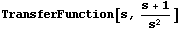
Out[2]=
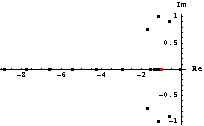
This plots the root loci. Note that because the system does not contain the parameter k, it is assumed to be the gain.
In[3]:=
RootLocusPlot accepts the options for ListPlot as well as several specific options that define the appearances of poles and zeros, and the number of points at which to sample the range for k.
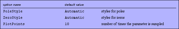
Options specific to RootLocusPlot.
As an example of using RootLocusPlot in feedback design, consider the system shown in Figure 5.1, for which we find coefficients k such that the damping ratio of the dominant closed-loop poles is 0.4 (cf. Ogata (1990)). The input or reference signal is denoted as r, the output or controlled signal is c, and the actuating or error signal is e.
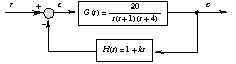
Figure 5.1. Example system for root locus construction.
This describes the block with the transfer function  . .
In[4]:=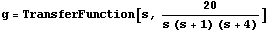
Out[4]=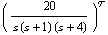
This defines the transfer function  . .
In[5]:=
Out[5]=
The open-loop system is formed by the serial connection of the blocks.
In[6]:=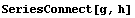
Out[6]=
The suitable values of k correspond to intersections of the root locus curve with the straight line depicting the locus of poles of the generic second-order system
for the chosen value of  , where , where  is the natural frequency and is the natural frequency and  is the damping ratio. is the damping ratio.
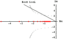
This plots root loci together with the line for the chosen value of  . The natural frequency . The natural frequency  has been picked quite arbitrarily, just to display the line in some bounds. Note that in this case parameter k is not the gain. As we can see, the line intersects the root locus branch somewhere between 5 and 6 points, and then again between points 14 and 15. has been picked quite arbitrarily, just to display the line in some bounds. Note that in this case parameter k is not the gain. As we can see, the line intersects the root locus branch somewhere between 5 and 6 points, and then again between points 14 and 15.
In[7]:=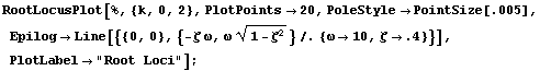
Roughly estimating that the intersections are 0.2 and 0.5 off the respective points, we get some estimates of parameter k that provide the required damping ratio.
In[8]:=
Out[8]=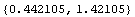
Here are the corresponding expressions for the closed-loop system.
In[9]:=
Out[9]=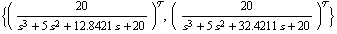
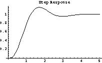
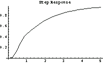
This simulates the step responses for the chosen values of k. The first system exhibits a faster response with reasonable overshoot compared to the second system.
In[10]:=
RootLocusAnimation complements RootLocusPlot and provides information on the direction of the evolution of root loci. The syntax for the two function is identical; the only exception is that the option PlotPoints is meaningless for the animation and is replaced by Frames, which determines the number of frames the animation should contain.


Animating the root loci.
|