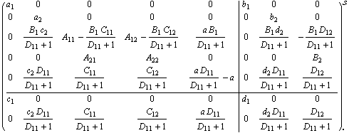
|
6.2 Arbitrary Interconnections
Systems more complex than the types described in the previous section can be constructed using GenericConnect. As with the elementary interconnecting functions, subsystems in GenericConnect can be supplied in either state-space or transfer function form. The result will be a state-space object if at least one system is in the StateSpace form. Note that, unlike elementary interconnections, GenericConnect always uses the state-space algorithm so it is advantageous to supply all input systems in the StateSpace form from the outset.


Building a complex system.
A necessary step in preparing the connections specification for GenericConnect is numbering all the inputs and all the outputs of the subsystems according to the order of the systems in the argument list (which can be arbitrary). The elements of the specification connections can be supplied as (1) a list of integers in the form {i,  , ,  , ,   indicating that input i gets its signal from summed outputs indicating that input i gets its signal from summed outputs  , (2) a list in the form {i, { , (2) a list in the form {i, { , ,   , { , { , ,   , ,   that allows the sign (negative or positive) for output that allows the sign (negative or positive) for output  to be set differently according to to be set differently according to  , or (3) a mix of the two. The type specification can be one of the reserved words Negative or Positive, with the default value depending on the option DefaultInputPort. , or (3) a mix of the two. The type specification can be one of the reserved words Negative or Positive, with the default value depending on the option DefaultInputPort.
As an example, consider connecting the three systems according to the block diagram in Figure 6.6. The subsystems were numbered in some order, and then the inputs and outputs were numbered sequentially in the order of the subsystems. In this way, the two inputs of system  (ss2) receive numbers (ss2) receive numbers  and and  , and the only output of this subsystem becomes output , and the only output of this subsystem becomes output  . The interconnections are then constructed using these numbers. Input . The interconnections are then constructed using these numbers. Input  receives its signal from outputs receives its signal from outputs  and and  , the latter taken with a negative sign, and input , the latter taken with a negative sign, and input  is connected to output 3. The aggregate has three external inputs, is connected to output 3. The aggregate has three external inputs,  and and  , and two external outputs, , and two external outputs,  and and  . .

Figure 6.6. Example of an arbitrary interconnection.
These are the components.
In[34]:=
Out[34]=
In[35]:=
Out[35]=
This creates the aggregate.
In[36]:=
Out[36]=
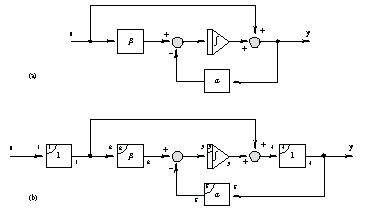
The algorithm implemented in GenericConnect (in which signals originate necessarily at the outputs of the blocks) imposes a limitation on the block diagram that GenericConnect can compute directly. The limitation is easy to overcome, however, by the addition of dummy blocks with a unit gain. For example, to construct a system containing the feed-forward and feedback paths as shown in Figure 6.7a, dummy blocks may be added as shown in Figure 6.7b.

Figure 6.7. Example of interconnection with dummy blocks added.
This computes the aggregate system shown in Figure 6.7. The output is a TransferFunction object since all input systems are supplied as transfer functions. Note that the variable from the first TransferFunction object, if any, is used in the result. Since, in this case, the first TransferFunction does not have a named variable, the result is the pure-function object. To emphasize the structure of the result we turn off the Control Format display.
In[37]:=
Out[37]=
Unless instructed otherwise, GenericConnect assumes that the outputs  in the connection specification {i, in the connection specification {i,  , ,  , ,   come to the summing input i with negative or positive signs as determined by the option DefaultInputPort. The default value of DefaultInputPort is Positive, which means that the outputs should be summed uninverted. come to the summing input i with negative or positive signs as determined by the option DefaultInputPort. The default value of DefaultInputPort is Positive, which means that the outputs should be summed uninverted.

Option to GenericConnect.
|