|
8.5 Dominant Subsystem
The controllability and observability Gramians in the example in the preceding section reveal the modes that are relatively small and, therefore, contribute little to the input-output characteristic. This suggests a way of reducing the order of the system by eliminating these weak modes. What is meant by "relatively small" is, of course, a matter of convention and will be addressed in the context of the option RejectionLevel later in this section.
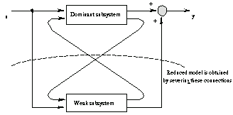
Schematically, the system breaks up into dominant and weak subsystems connected as shown in Figure 8.1. DominantSubsystem can be used to select the dominant part.

Figure 8.1. Model reduction based on decomposing the system into its dominant and weak parts.


Model reduction by selection of the dominant subsystem.
A reduced-order model of the system original can be found by selecting the dominant subsystem.
In[25]:=
Out[25]=
Similarly to the function MinimalRealization, DominantSubsystem takes the option ReductionMethod. With the default Automatic value for this option, DominantSubsystem may use the structural information about the input system if it is available (if, for example, the system is already in the internally balanced form). Otherwise, the function starts from constructing the internally balanced realization and then selects the dominant part, as set by the option RejectionLevel. With ReductionMethod  InternallyBalancedForm, DominantSubsystem always uses the internally balanced form to select the dominant part. DominantSubsystem inherits options from InternallyBalancedForm. InternallyBalancedForm, DominantSubsystem always uses the internally balanced form to select the dominant part. DominantSubsystem inherits options from InternallyBalancedForm.

The option specific to DominantSubsystem.
If the default value of RejectionLevel is not appropriate for the particular case, the user may find the internally balanced realization "manually" and then choose a suitable value for RejectionLevel.
Because we do have the internally balanced realization of the system original, we use it to find the second-order reduced model.
In[26]:=
Out[26]=
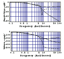
This creates the Bode plots for the three systems and displays them at once. The solid line is for the initial system, and the dashed and dashed-dotted ones are for the third- and second-order reduced models, respectively. Note that in the first plot we set up a plot range sufficient to display all three graphs, and in the second plot we tweak PlotPoints for the phase unwrapping mechanism to operate correctly.
In[27]:=

As we can see, in the reduced models the low-frequency behavior is preserved while the high-frequency (fast) states are eliminated.
|