6.1.3 3D Cam ConstraintsThe 3D cam constraints provided by Modeler3D cover eight elementary cases of a cam and follower relationship. The 3D cam profiles used by Modeler3D fall into two basic categories: spatial surfaces and spatial curves. Spatial surfaces are defined by the locus of a single 3D point, the coordinates of which are a function of two independent parameters. Space curves are defined by a point that is a function of a single parameter.
In practice many 3D cam profiles are 2D in nature, in which case they are modeled using the techniques that were developed in Section 6.1.2 on 2D cams. Any 2D cam profile can be converted to a 3D space curve by inserting or appending a third constant coordinate to the 2D locus point.
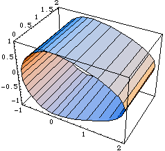
Even when a true 3D surface profile is required, it can often be built up from the sum of two 2D curves that are functions of two different parameters. The following example uses one of the 2D cam profiles that was developed in Section 6.1.1 to generate a 3D cam surface. The only change to the 2D cam is the addition of the parameter t that directly specifies the local y coordinate of the cam. This example would serve as a valid cam profile for any Modeler3D cam constraint function. Here is a valid Modeler3D cam profile. Here is a plot of the cam profile.

Out[21]= |  |
Note that although the Modeler3D cam constraints constrain one degree of freedom in the model (or two in the case of CurveToPoint2), they actually add between two and five equations to the model. This is because each cam constraint also adds one to four symbols to the model's dependent variable list (two parameters for each surface and one for each curve) for a net loss of one or two degrees of freedom. This anomaly is of no consequence to the user except when a cam constraint is used within TimeSwitch or StageSwitch. In these cases the added symbols in the cam constraint must be dealt with in the other stages of the switch function, usually by using the Modeler3D Constraint function to set the added symbols equal to a constant. Space curve constraints. Spatial surface constraints. Note that each symbol in a cam constraint must be accompanied by a numerical initial guess, guess.
The locus point that is passed to a Modeler3D cam constraint must be a valid Modeler3D point object containing the parametrically defined point. Also, the point must evaluate to a three-element list of differentiable expressions that are functionally dependent on the parameter alpha, at the time that the constraints are processed with SetConstraints. This is because the locus point is differentiated with respect to its controlling parameters by the SetConstraints function. Thus, if the locus point is not an explicit function of its parameters when passed to SetConstraints its derivative will be zero.
Note that all cam relationships are restricted to being in point contact. If two cam surfaces are defined such that they instantaneously have line contact instead of point contact, a singularity will result.
Some cam constraints are sensitive to which side of the cam surface the follower is on. The outside of a surface is defined as the side of the positive normal, which is the cross product of the direction of the surface gradient with respect to the first parameter and the direction of the surface gradient with respect to the second parameter.
CamPlot is a special graphics function provided to parametrically plot the cam profiles in global coordinates. Note that CamPlot returns a Mathematica graphics object, with the head Graphics, not a graphics primitive like most of the other Modeler3D graphics functions.

A cam-specific graphics function. CamPlot produces the same output as would ParametricPlot, except that CamPlot transforms the cam profile into the global coordinate system. CamPlot does not evaluate directly to a Graphics object because numeric values for the coordinate transformation are not available. Instead, CamPlot returns a SysPlot object that evaluates to a Graphics object when numbers are available for the transformation. This loads the Modeler3D package. CamPlot returns a SysPlot object.
Out[23]= |  |
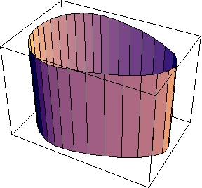
When numbers are available for X2, Y2, and so on, the SysPlot object evaluates to a Graphics object. Here we show the repositioned cam surface.

Out[24]= |  |
|