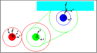
6.2.2 Example 2D Gear MechanismTo demonstrate the use of Modeler2D gear constraints a 2D model is developed that uses a pair of gears, a pair of pulleys and a belt, and a rack and pinion. The input to the model is the specified rotation of the drive gear. This, in turn, rotates the driven gear, which is the same body as the drive pulley. The drive pulley rotates the driven pulley, which is the same body as the pinion. The rotation of the pinion causes the rack to translate. Here is a 2D gear-drive mechanism graphic.

BodiesFive bodies are used in the gear-drive model. No body objects are defined because no explicit point coordinates are used in the model. Names are defined for each of the body numbers in the model. ConstraintsEight constraints are required to model the gear-drive mechanism. A Revolute2 constraint locates the center of the drive gear at the origin of the ground body.A RotationLock1 constraint controls the rotation of the drive gear.A TwoGears2 constraint controls the rotation of the drive pulley and specifies the distance between the drive gear and the drive pulley.A RelativeY1 constraint prevents the drive pulley from orbiting the drive gear.A TwoPulleys2 constraint controls the rotation of the pinion and specifies the distance between the drive pulley and the pinion.A RelativeY1 constraint prevents the pinion from orbiting the drive pulley.A RackAndPinion2 constraint controls the translation of the rack and specifies the orthogonal distance between the rack axis and the pinion center.A Parallel1 constraint forces the rack axis to be parallel to a horizontal line on the ground, which prevents the rack from orbiting the pinion. Here are the constraints for the gear model. RuntimeInitial guesses for the drive pulley, rack, and pinion must be set or the model will not converge. Almost any guesses greater than zero will do. This sets the initial guesses for the next solution attempt only.
Out[11]= |  |
Because of the presence of time T in the driving constraint, the model can be run through its intended range of motion by varying T directly with the SolveMech command. The numerical value of T specifies the angular coordinate of the drive gear. Now run the model at T = 0.05.
Out[12]= |  |
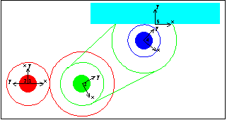
Now run the model at T = 0.25.
Out[13]= |  |
Here is the gear-drive mechanism at T = 0.25.

|