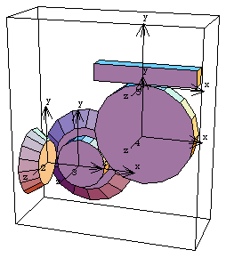
6.2.4 Example 3D Gear MechanismTo demonstrate the use of Modeler3D gear constraints a 3D model is developed that uses a pair of orthogonal bevel gears, a pair of parallel spur gears, and a rack and pinion gear set. The input to the model is the specified rotation of the first bevel gear, the drive bevel. This, in turn, rotates the driven bevel gear, which is the same body as the drive spur gear. The drive spur rotates the driven spur, which is the same body as the pinion. The rotation of the pinion causes the rack to translate. Here is the 3D gear-drive mechanism.

BodiesFive bodies are used in the gear-drive model. No body objects are defined because no explicit point coordinates are used in the model. Names are defined for each of the body numbers in the model. ConstraintsEight constraints are required to model the gear-drive mechanism. A Revolute5 constraint controls the rotational axis of the drive bevel. The drive bevel rotates about an axis originating at the global origin and pointing in the global X direction, which is coincident with the drive bevel's local x axis.A ProjectedAngle1 constraint specifies the rotation of the drive bevel.An OrthogonalGears5 constraint enforces the gear relationship between the drive bevel and the driven bevel (drive spur). The Axis objects that are used to specify the axes of each gear contain several important elements. The origins of the two axes are to be adjacent, thus they are located on the gear axes at the intended point of intersection of the axes. The local coordinate axes of the drive spur are initially rotationally aligned with the local axes of the drive bevel. Thus, the reference direction of each gear is initially parallel to the rotational axis of its neighbor, which results in an orientation constant of zero. Note also that these are straight cut bevel gears, so the offset distance between their axes is also zero.A RelativeY1 constraint removes the one remaining degree of freedom from the drive spur, its freedom to orbit drive bevel.A ParallelGears5 constraint enforces the gear relationship between the drive spur and the driven spur (pinion). The rotational axes of these two gears are to be parallel, so they both point in the local z direction. The orientation constant allows the two gears to be initially aligned with the global axes.A RelativeY1 constraint prevents the pinion from orbiting the drive spur.A RackAndPinion5 constraint controls the translation of the rack and the orthogonal distance between the rack axis and the pinion center. The radius of the rack is specified as - 3.0 to put the pinion on the correct side of the rack for this model.A Orthogonal1 constraint prevents the rack from orbiting the pinion.Here is the complete constraint set for the gear-drive model. RuntimeInitial guesses for the rack and pinion must be set or the model will not converge. This sets the necessary initial guesses. Because of the presence of T in the driving constraint, the model can be run through its intended range of motion by varying T directly with the SolveMech command. The numerical value of T specifies the angular coordinate of the drive bevel. Now run the model at T = 0.05.
Out[26]= |  |
Now run the model at T = 0.25.
Out[27]= |  |
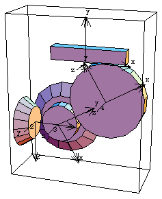
Here is the gear-drive mechanism at T = 0.25.

From the sizes of the gears in this model and the fact that the drive bevel is turning at one revolution per second, we can calculate what the velocity of the rack should be. This can also be found directly from the velocity of the rack in the Modeler3D model.

Here is the rack velocity, calculated explicitly and from the model.
Out[28]= |  |
Out[29]= |  |
|