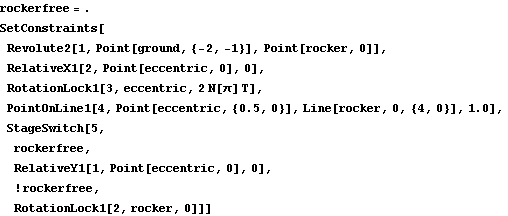
5.1.2 Rocker Example MechanismTo demonstrate the use of the Modeler2D StageSwitch function, a 2D model of a rocker arm driven by an eccentric is developed. The model consists of two moving bodies, the eccentric and the rocker.
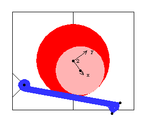
This mechanism has two distinct modes of operation that are toggled via the StageSwitch function. The first mode of operation is for the eccentric to be rotated about a stationary axis, forcing the rocker to reciprocate by its contact with the eccentric. The second mode is for the eccentric to be rotated about an axis that is unconstrained in the vertical direction while the rocker is constrained to be stationary. This causes the eccentric to rise and fall as a result of its rotation. Here is the 2D rocker model graphic.
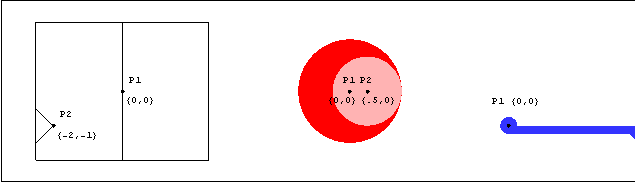
Bodies Three bodies are used in the rocker mechanism model. The ground (body 1) requires two points.
P1 is the rotational axis of the eccentric at {0, 0}.
P2 is the rotational axis of the rocker at {- 2, - 1}.The eccentric (body2) requires two points.
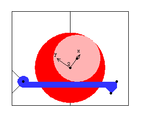
P1 is the rotational axis of the eccentric at local coordinates {0, 0}.
P2 is the center of the eccentric disk at local coordinates {0.5, 0}.The rocker (body 3) requires two points.
P1 is the rotational axis of the rocker at local coordinates {0, 0}.
P2 is the right end of the rocker face at local coordinates {4, 0}.Here are all of the bodies in the rocker model.
Names are defined for each of the body numbers in the model. SetBodies is used only to set a nonzero initial guess for the rocker. ConstraintsFour regular constraints and one StageSwitch constraint are used to model the rocker mechanism. A Revolute2 constraint forces the axis of the rocker to be coincident with its pivot point on the ground. This constrains two degrees of freedom, X and Y displacement of the rocker.A RelativeX1 constraint specifies the X coordinate of the rotational axis of the eccentric.A RotationLock1 constraint controls the angular coordinate of the eccentric. This driving constraint is used to specify the rotation of the eccentric as a function of T.A PointOnLine1 constraint enforces that the surface of the eccentric disk, which has a radius of one unit, remains in contact with the face of the rocker.A StageSwitch constraint with two stages constrains the remaining one degree of freedom. Which mode of operation is active is determined by the boolean value of rockerfree.
 If rockerfree is True, a RelativeY1 constraint specifies the Y coordinate of the axis of the eccentric, leaving the rocker free to reciprocate. If rockerfree is True, a RelativeY1 constraint specifies the Y coordinate of the axis of the eccentric, leaving the rocker free to reciprocate.
If rockerfree is False, a RotationLock1 constraint enforces that the rocker does not rotate, leaving the eccentric free to reciprocate vertically. Here is the complete rocker mechanism, built in one step. RuntimeThe rocker mechanism model is first run with rockerfree set to True. This enables the first stage of the StageSwitch constraint. The model is first run at T = 0.15 with the rocker free to rotate.
Out[13]= |  |
Here is the rocker mechanism with rockerfree = True.
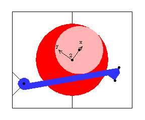
Now the mechanism model is run with rockerfree set to False. This enables the second stage of the StageSwitch constraint. The model is now run at T = 0.15 with the rocker fixed.
Out[15]= |  |
Here is the rocker mechanism with rockerfree = False.
|