5.1 Stage Switching ConstraintsA StageSwitch constraint is nothing more than a compound constraint that contains several normal Mech constraints and lets the user specify which one is active. This function can be used to model any mechanism that has more than one mode of operation, and it is desired to automatically switch the model from one mode to another. 5.1.1 StageSwitchA multistage mechanism constraint-switching function. A StageSwitch constraint returns an error if any of the test expressions fail to return either True or False at runtime. Because StageSwitch does evaluate its own arguments immediately, unlike Which or If, test expressions such as SameQ should not be used. This is because SameQ evaluates immediately to True or False instead of waiting until some future condition changes. Also, a StageSwitch constraint is invalid if all of the test expressions return False at runtime because no constraint is applied to the model.
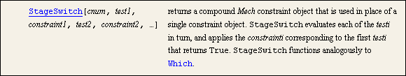
Each of the constraints supplied to the StageSwitch constraint are standard Mech constraint objects or lists of constraint objects. Each constraint or list of constraints must constrain the same number of degrees of freedom. Note that the constraint numbers of the constraints that are inside of the StageSwitch constraint are irrelevant. The constraint number of the entire StageSwitch constraint is the only one that is used to reference the constraint. Examples This loads the Modeler2D package. The following example shows how StageSwitch (constraint 1) might be used to model a pin on a slider that slides in one of two straight tracks on the ground body. Which track to use is determined by the value of the user-defined symbol whichtrack, which must be either 1 or 2. Here is a valid StageSwitch constraint.
Out[4]= |  |
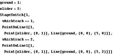
The following example shows how a StageSwitch constraint that constrains two degrees of freedom might be implemented. The first constraint in the StageSwitch constraint forces the origin of the slider to be coincident with the origin of the ground. If the value of the user-defined symbol pressure rises above 100 units, the second constraint pair becomes active and forces the origin of the slider to lie upon a line and be positioned as a function of the value of pressure. Here is a valid StageSwitch constraint.
Out[5]= |  |
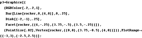
5.1.2 Rocker Example MechanismTo demonstrate the use of the Modeler2D StageSwitch function, a 2D model of a rocker arm driven by an eccentric is developed. The model consists of two moving bodies, the eccentric and the rocker.
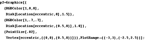
This mechanism has two distinct modes of operation that are toggled via the StageSwitch function. The first mode of operation is for the eccentric to be rotated about a stationary axis, forcing the rocker to reciprocate by its contact with the eccentric. The second mode is for the eccentric to be rotated about an axis that is unconstrained in the vertical direction while the rocker is constrained to be stationary. This causes the eccentric to rise and fall as a result of its rotation. Here is the 2D rocker model graphic.
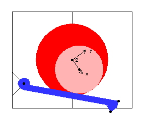
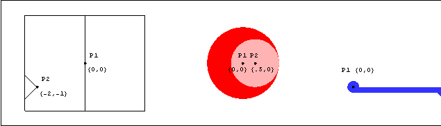
Bodies Three bodies are used in the rocker mechanism model. The ground (body 1) requires two points.
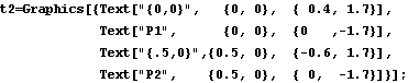
P1 is the rotational axis of the eccentric at {0, 0}.
P2 is the rotational axis of the rocker at {- 2, - 1}.The eccentric (body2) requires two points.
P1 is the rotational axis of the eccentric at local coordinates {0, 0}.
P2 is the center of the eccentric disk at local coordinates {0.5, 0}.The rocker (body 3) requires two points.
P1 is the rotational axis of the rocker at local coordinates {0, 0}.
P2 is the right end of the rocker face at local coordinates {4, 0}.Here are all of the bodies in the rocker model.
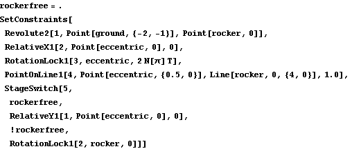
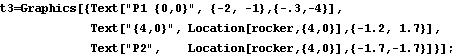
Names are defined for each of the body numbers in the model. SetBodies is used only to set a nonzero initial guess for the rocker. ConstraintsFour regular constraints and one StageSwitch constraint are used to model the rocker mechanism. A Revolute2 constraint forces the axis of the rocker to be coincident with its pivot point on the ground. This constrains two degrees of freedom, X and Y displacement of the rocker.A RelativeX1 constraint specifies the X coordinate of the rotational axis of the eccentric.A RotationLock1 constraint controls the angular coordinate of the eccentric. This driving constraint is used to specify the rotation of the eccentric as a function of T.A PointOnLine1 constraint enforces that the surface of the eccentric disk, which has a radius of one unit, remains in contact with the face of the rocker.A StageSwitch constraint with two stages constrains the remaining one degree of freedom. Which mode of operation is active is determined by the boolean value of rockerfree.
 If rockerfree is True, a RelativeY1 constraint specifies the Y coordinate of the axis of the eccentric, leaving the rocker free to reciprocate. If rockerfree is True, a RelativeY1 constraint specifies the Y coordinate of the axis of the eccentric, leaving the rocker free to reciprocate.
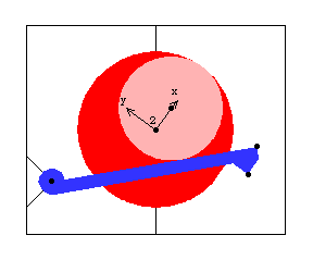
If rockerfree is False, a RotationLock1 constraint enforces that the rocker does not rotate, leaving the eccentric free to reciprocate vertically. Here is the complete rocker mechanism, built in one step. RuntimeThe rocker mechanism model is first run with rockerfree set to True. This enables the first stage of the StageSwitch constraint. The model is first run at T = 0.15 with the rocker free to rotate.
Out[13]= |  |
Here is the rocker mechanism with rockerfree = True.
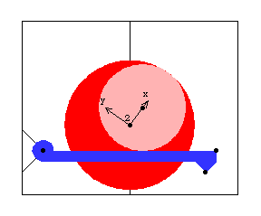
Now the mechanism model is run with rockerfree set to False. This enables the second stage of the StageSwitch constraint. The model is now run at T = 0.15 with the rocker fixed.
Out[15]= |  |
Here is the rocker mechanism with rockerfree = False.
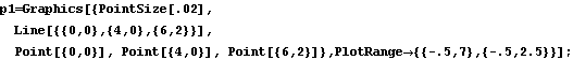
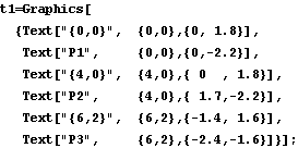
Undocumented Graphics GenerationThe following inputs generate the graphics in this section. These Modeler2D commands are defined in Chapter 3. 5.1.3 Slider-Ramp Example MechanismAnother usage of the StageSwitch constraint is to switch from one stage of operation to another when such switching is the normal progression of operation of the mechanism. To demonstrate this usage a 2D model of a slider on a ramp is developed. The model has only one moving body, the slider.
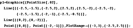
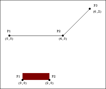
This mechanism has two distinct modes of operation. First, the slider travels across a horizontal surface until it encounters an inclined ramp. As the slider progresses further, its front edge leaves the horizontal plane and begins to slide up the inclined ramp. StageSwitch is used to switch between these modes by defining the test expressions in the StageSwitch constraint to test explicitly whether or not the corner of the slider has traveled beyond the bottom of the ramp. Here is a graphic of the 2D slider-ramp model.
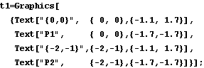
Bodies Two bodies are needed in the slider-ramp mechanism model. The ground (body 1) requires three points.
P1 is the beginning of the horizontal ramp at {0, 0}.
P2 is the end of the horizontal ramp and the beginning of the inclined ramp at {4, 0}.
P3 is the end of the inclined ramp at {6, 2}.The slider (body 2) requires two points.
P1 is the left bottom corner of the slider at local coordinates {0, 0}.
P2 is the right bottom corner of the slider at local coordinates {2, 0}.Here are both the bodies in the slider-ramp model.
Names are defined for each of the body numbers in the model. ConstraintsTwo regular constraints and one StageSwitch constraint are used to model the slider-ramp mechanism. A RelativeX1 constraint specifies the X coordinate of the left bottom corner of the slider as a function of time T.A PointOnLine1 constraint enforces that the left bottom corner of the slider remains in contact with the horizontal surface of the ramp.A StageSwitch constraint with two stages eliminates the one remaining degree of freedom:
A PointOnLine1 constraint is used to place the right bottom corner of the slider on the horizontal surface if it is still to the left of the ramp.
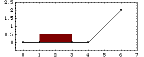
A PointOnLine1 constraint is used to place the right bottom corner of the slider on the inclined ramp if it has passed to the right of the ramp.Which stage of operation is active is determined by the value of a test expression that is a function of Modeler2D dependent variables. The test expression measures whether or not the right bottom corner of the slider has progressed far enough to the right to be on the inclined ramp. Here is the slider-ramp mechanism built in one step. RuntimeThe slider-ramp mechanism model can be run at any time, T, up to T = 4 with valid results. After T = 4, the left bottom corner of the slider passes the inclined ramp, but it does not travel up the ramp because the constraints have not been written to accommodate this. This runs the model at T = 1.
Out[19]= |  |
The slider-ramp mechanism is still on the horizontal segment of the ramp.
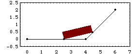
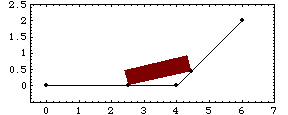
Now the model is run at T = 2.5, which puts the slider part way up the ramp.
Out[20]= |  |
Here is the result.
Undocumented Graphics GenerationThe following inputs generate the graphics in this section. These Modeler2D commands are defined in Chapter 3.
|