5.2.2 Detent Mechanism ExampleTo demonstrate the use of the Modeler2D TimeSwitch function a 2D model of a detent mechanism is developed. The model consists of two moving bodies, a slider and a detent plunger.
The detent mechanism goes through seven distinct stages of operation as the detenter passes across the slider, down into the detent notch, and back out. These stages are progressively activated via the TimeSwitch function as follows. In stage 1 the detenter travels across the right top surface of the slider.
In stage 2 the detenter travels around the corner that leads into the detent notch.
In stage 3 the detenter travels down the inclined right side of the detent notch.
In stage 4 the detenter travels around the round bottom of the detent notch.
In stage 5 the detenter travels up the inclined left side of the detent notch.
In stage 6 the detenter travels around the corner that leads out of the detent notch.
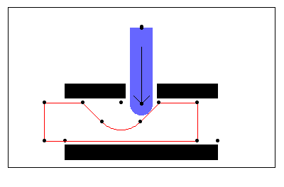
In stage 7 the detenter travels across the left top surface of the slider. Here is the 2D detent model graphic.

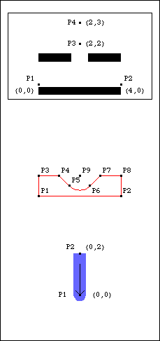
BodiesThree body objects are defined for the detent mechanism model. Four points are defined on the ground body (body 1).
P1 and P2 are two points that define the horizontal line on which the slider translates.
P3 and P4 are two points that define the vertical line on which the detenter translates.Nine points are defined on the slider (body 2).
P1 and P2 are two points that define the horizontal translation line of the slider.
P3 to P8 are a series of points defining the detent notch in the top surface of the slider.
P9 is the center point of the circular bottom of the detent notch.Two points are defined on the detenter (body 3).
P1 and P2 are two points defining the vertical translation axis of the detenter.Names for each body number in the model are defined. Here are all three bodies in the detent mechanism model.

The body objects are incorporated into the model. Constraints Three regular constraints and one TimeSwitch constraint are used to model the detent mechanism. A Translate2 constraint forces a horizontal line on the slider to be coincident with a horizontal line on the ground, allowing the slider to translate in the X direction only.A Translate2 constraint forces a vertical line on the detenter to be coincident with a vertical line on the ground, allowing the detenter to translate in the Y direction only.A RelativeX1 constraint controls the X coordinate of the slider. This driving constraint is used to specify the position of the slider as a function of time T.The TimeSwitch constrains the one remaining degree of freedom:
 Four of the seven stages of operation (1, 3, 5, and 7) are modeled by PointOnLine1 constraints that place the center of the detenter tip a specified distance (detenter tip radius) away from various lines on the slider. Four of the seven stages of operation (1, 3, 5, and 7) are modeled by PointOnLine1 constraints that place the center of the detenter tip a specified distance (detenter tip radius) away from various lines on the slider.
 The second and sixth stages, in which the detenter tip moves around sharp corners on the slider, are modeled with RelativeDistance1 constraints that place the center of the detenter tip a specified distance (detenter tip radius) away from the sharp corners on the slider. The second and sixth stages, in which the detenter tip moves around sharp corners on the slider, are modeled with RelativeDistance1 constraints that place the center of the detenter tip a specified distance (detenter tip radius) away from the sharp corners on the slider.
 The fourth stage, in which the detenter tip is traveling around the arc at the bottom of the detent notch, is also modeled with a RelativeDistance1 constraint that places the center of the detenter tip a specified distance (detent notch radius minus detenter tip radius) away from the center point of the arc. The fourth stage, in which the detenter tip is traveling around the arc at the bottom of the detent notch, is also modeled with a RelativeDistance1 constraint that places the center of the detenter tip a specified distance (detent notch radius minus detenter tip radius) away from the center point of the arc.The exact values of the switch times given as arguments to the TimeSwitch constraint are not known. The symbols given in place of switch times (tm2, tm3, etc.) are set to approximate values before running the model. The exact switch times will be determined later with FindSwitchTime. Here are the three regular constraints. Here is the seven-stage TimeSwitch constraint. The constraints are incorporated into the current model. RuntimeBefore the detent model can be run, the switch times used in the TimeSwitch constraint (tm2, tm3, etc.) must be given numeric values. Here are guesses for switch times. Now the model is run at T = - 1.3.
Out[23]= |  |
Here is the detent mechanism at T = - 1.3.

Now the model is run twice more at T = - 0.5 and T = - 0.1.
Out[24]= |  |
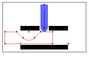
Here is the detent mechanism at the two new solution points.

Note again that the current values of the switch times (tm2, tm3, etc.) are merely guesses. If the model is run at values very close to those times, incorrect results will be generated whenever the model uses the wrong constraint. The exact values of the switch times are found in Section 5.2.3 with the FindSwitchTime function.
|