3.5.3 Example Mechanism GraphicsThe spatial slider-crank mechanism model that was developed in Section 3.2 is used to demonstrate the use of Modeler3D graphics functions to create an image of a mechanism model. Creating a complex mechanism image often requires more lines of Mathematica code than were used in the kinematic model of the mechanism. This is because of the terse nature of the data required to kinematically describe a mechanism. A kinematic model uses only a small number of points in space to define rotational and translational axes that tie the bodies together, while the mechanism image requires much more information about the shape of the bodies in the model.
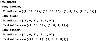
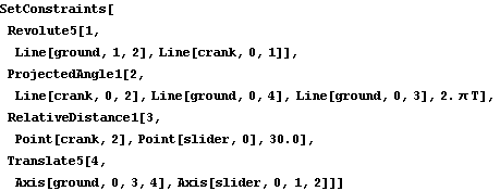
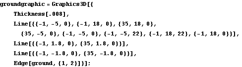
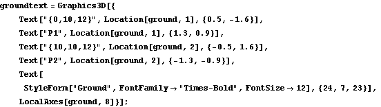
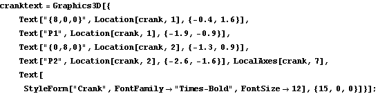
The spatial slider-crank model is redefined as follows in abbreviated form. See Section 3.2 for a full description of this mechanism model. Here is the complete definition of the slider-crank model. To demonstrate the use of the graphics functions the image of the slider-crank mechanism that is displayed in the preceding sections is built. These images are generated with a mix of Modeler3D graphics functions and built-in Mathematica graphics primitives. GroundThe ground body of the slider-crank mechanism was generated using mostly built-in Mathematica graphics primitives. The Modeler3D Edge function was used to generate a line on the crank axis referencing local points by their point numbers. Here is the ground body graphic. The text that was displayed with the ground body was generated entirely with the built-in Mathematica Text function, except for the axes at the global coordinate origin, generated with the Modeler3D LocalAxes function, and the use of the Location function to reference the global coordinates of local point numbers on the ground body. Here is the ground body annotation. Here is the result.
Out[30]= |  |
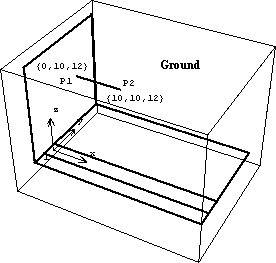
CrankThe crank graphic uses the Modeler3D Cylinder function to generate a very short cylinder. The cylinder is only one unit long because the line that defines its axis is one unit long, while the radius of the cylinder is ten units as specified. Here is the crank body graphic. The text that was displayed with the crank graphic also used the Location function to specify the global coordinates of the text so that the text moves with the crank. Here is the crank annotation. Because the coordinates of some of the elements in crankgraphic and cranktext are now functions of Modeler3D dependent variables, X2, Y2, and so on, a Modeler3D solution rule must be applied before they can be displayed. Note the use of SolveMech in the following input. The rules that are returned by SolveMech determine where the crank is located in 3D space. Here is the result.
Out[33]= |  |
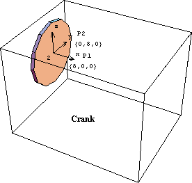
SliderThe slider graphic uses the Modeler3D Box function to generate the rectangular box form of the slider. Here is the slider graphic. Here is the slider annotation. Like the crank graphic, the coordinates in the slider graphic are functions of Modeler3D dependent variables. Thus, a solution rule must be applied to display the graphic. Show it.
Out[36]= |  |
Connecting RodThe connecting rod graphic uses the Modeler3D Cylinder function again to generate a long, thin cylinder spanning from the crank to the slider. Here is the connecting rod graphic. Here is the connecting rod annotation. Here is the result.
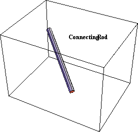
Out[39]= |  |
To show the complete quick-return mechanism, all of the graphics objects are put together and displayed subject to a Modeler3D solution rule. Here is the complete slider-crank mechanism at T = 0.10.
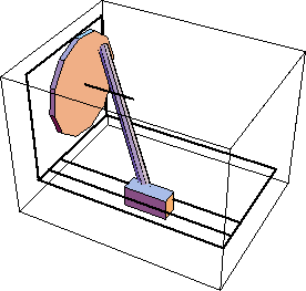
Out[40]= |  |
Here is the mechanism at T = 0.25, shown from a different perspective.
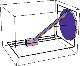
Out[41]= |  |
|