|
12. Performance Improvement OverviewThis chapter is intended to help the user improve the performance of kinematic and dynamic models built with MechanicalSystems. The symbolic mathematical systems that are generated by Mech can become quite large, causing their evaluation to proceed very slowly. There is no single trick that will speed up the evaluation of all Mech models, except buying a faster computer, and a technique that successfully accelerates one type of model may have the opposite affect on another. However, attention to the guidelines in the following sections will generally prevent the user from building a particularly bad model, and may lead to large reductions in run time. 12.1 Updating SolutionsThe simplest way to get a MechanicalSystems model to run faster is to ask it to do less work. This is usually accomplished by keeping track of and reusing results that have already been obtained, instead of generating them again.
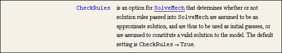
When mechanism velocity or acceleration data is needed, or static or dynamic constraint reaction forces, the complete location solution must first be calculated. If this has already been done, the CheckRules option prevents Mech from doing it again. An option for SolveMech. If CheckRules -> False is specified, the solution rules that are passed to SolveMech are not checked against the constraints, they are simply passed to the next phase of the solution block. This is useful if a set of lower-order solution rules has already been obtained (e.g., location solution) and a set of higher-order (i.e., velocity or acceleration) rules is desired.
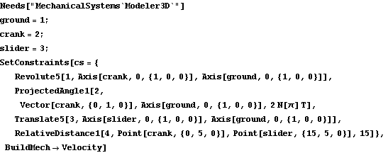
The following example uses a spatial slider-crank model to demonstrate the time savings that can be realized by updating higher-order solutions without regenerating lower-order data. The example mechanism consists of two bodies, a crank and a slider, and a connecting rod that is simply a distance constraint. No initial guesses are needed for the model because both the crank and the slider are initially coincident with the local origin. Here is an entire slider-crank model built in one step. Here is a solution to the model near T = 0.
Out[6]= |  |
To show the difference between regenerating solutions, updating solutions, and updating solutions without checking validity, a series of location solutions are generated and then updated to velocity solutions. This generates 21 solutions to the model as time goes from 0 to 1. This generates the complete location and velocity solution at 21 points.
Out[9]= |  |
This generates the complete location and velocity solution using the location rules already calculated as initial guesses at each step.
Out[10]= |  |
This generates only the new velocity solution using the location rules already calculated without checking that they in fact satisfy the constraints.
Out[11]= |  |
This same technique can be used to update a location solution to a static solution, or any other combination of the solution levels generated by SolveMech. If CheckRules -> False is specified, the only part of the solution that is actually calculated anew is the part explicitly requested by the solution option, and any parts of the solution that are not present in the solution rules that are to be updated. 12.2 Simplifying ExpressionsThis section covers some of the ways that a MechanicalSystems model can be algebraically simplified to improve performance. 12.2.1 Local Coordinate ChoicesMechanicalSystems allows considerable flexibility in defining geometric constraints and forcing functions. The points and lines that are used to make up these elements can be located anywhere in the local coordinate system of any body in the model. However, all points are not created equal, in terms of efficiency, and choosing a more complicated representation of a geometric relationship over a simpler one can result in large changes in the time required to run a model.
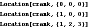
In general, it is best to use the local origin of a body whenever possible in defining constraint or load functions because the local origin is represented by a much simpler expression than a non-origin point. When the local origin cannot be used, the more zeros there are in the local coordinates of a point, the better. Here are the symbolic representations of three points on the crank.
Out[12]= |  |
Out[13]= |  |
Out[14]= | 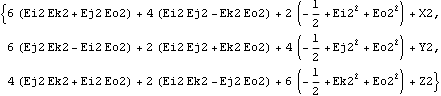 |
Obviously, it takes less time to evaluate the first of these three expressions than it does to evaluate the others. Further, since all points on the ground body are constant, use points on the ground body over points on other bodies whenever possible, even over the local origins of the other bodies.
These guidelines also apply to the definition of Line, Plane, and Axis objects; use the ground body if possible. However, it is usually better to use two or three points on the same body to define a Line or Plane object than it is to use one point on the ground and other points on another body.
Finally, one point where the relative simplicity of the local origin is of great importance is in the location of the centroid of a dynamic model. While Mech does allow the centroid to be placed arbitrarily on a body, moving the centroid off of the local origin of a body results in a great increase in the complexity of the model's mass matrix. The mass matrix of a 3D body in local coordinates is a  block diagonal constant matrix (completely diagonal if the products of inertia are zero), if the centroid is located at the local origin. If the centroid is moved off of the local origin, the mass matrix becomes a block diagonal constant matrix (completely diagonal if the products of inertia are zero), if the centroid is located at the local origin. If the centroid is moved off of the local origin, the mass matrix becomes a  nonconstant full matrix. This is especially important when integrating the equations of motion, when the mass matrix must be evaluated at every time step. nonconstant full matrix. This is especially important when integrating the equations of motion, when the mass matrix must be evaluated at every time step. 12.2.2 Constraint and Load ChoicesThe entire set of constraint functions provided by Mech is quite redundant. Almost any geometric constraint can be duplicated by some other constraint or combination of constraints. However, the algebraic expressions generated by functionally identical constraints can be quite different. It is important to use the simplest possible representation of a mechanism joint to reduce the size of the model.
The one time when a more complicated constraint set should be considered is when it is possible to remove a body from a model by replacing the entire body with a compound constraint. The OrthoRevolute4 and ParaRevolute4 constraints in Modeler3D are good candidates for replacing entire bodies in a model, as is the RelativeDistance1 constraint that is commonly used to replace a connecting rod. It is often possible to eliminate multiple bodies, even interlinked bodies, with a correctly chosen compound constraint.
A body cannot be eliminated from a mechanism when the inertia of the body is relevant to the analysis. But even this has an exception: the gyroscopic forces associated with a body that is spinning rapidly about an axis of symmetry can be duplicated by a GyroMoment forcing function, thus eliminating the body itself from the model. 12.2.3 Simplifying with MathematicaAfter the constraints and loads used to build the Mech model have been chosen as carefully as possible to simplify the model, Mathematica's Simplify or Expand functions can be applied to all of the internal expressions generated by Mech by setting $MechProcessFunction equal to Simplify, Expand, TrigExpand, or any other routine designed to simplify expressions or optimize them for efficient evaluation.
Because many of the internal expressions generated by MechanicalSystems are very large, applying Simplify to all of them can be quite computationally expensive in itself. The performance of SetConstraints and related model-building functions can be degraded significantly in exchange for better performance from SolveMech. This will cause Simplify and Chop to be applied to all internal expressions generated by Mech.
Out[15]= |  |
12.3 Compiling ExpressionsMost MechanicalSystems functions that use an iterative Newton-Rhapson solver or numerical integration accept the Compiled option. Setting Compiled -> True can result in a substantial reduction in run time, at the expense of some increase in the time required to build the model. However, Mathematica's ability to compile expressions is not universal. There are some types of algebraic expressions that cannot be compiled. If an algebraic expression within a Mech model contains such a form, it cannot be compiled.
The spatial slider-crank model is rebuilt with the Compiled option to demonstrate the speed increase that is realized by compiling the model. This rebuilds the constraints in compiled form. The BuildMech option forces an immediate build of the velocity equations, which prevents the time required to build them from being included in the timing. This generates the complete location and velocity solution at 21 points in about half the time that was required without the Compiled option.
Out[18]= |  |
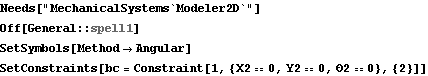
12.4 Coordinate SystemsMechanicalSystems allows models to be built in several different coordinate systems: Euler and Angular in two dimensions, and Euler, Global Angular, and Local Angular in three dimensions. If the mechanism is planar, use a planar model because 2D models run much faster than 3D models. 12.4.1 2D Coordinate SystemsThere is no clear rule for the best choice of coordinate systems in planar or spatial models, with respect to minimizing run time. In 2D, it would seem that Angular would always be better, because only three constraint expressions are required per body, instead of four. But, this is largely offset by the fact that the 2D degenerate Euler coordinate system uses no trigonometric functions in the formulation of geometric constraints, and that the first and second derivatives of expressions written in terms of 2D Euler parameters are very simple. This sets the 2D coordinate system to Angular and defines a bogus constraint so that the symbolic derivatives of the coordinates of body 2 are defined by SetConstraints. Here are the location and velocity of an arbitrary point in angular coordinates.
Out[5]= |  |
Out[6]= |  |
Now the coordinate system is changed to Euler. Here are the location and velocity of an arbitrary point in 2D Euler coordinates.
Out[9]= |  |
Out[10]= |  |
In conclusion, models that are to be used for acceleration analysis may run faster if the degenerate Euler coordinates are used, but they may not. 12.4.2 3D Coordinate SystemsIn 3D models, there is no difference between the respective coordinate systems with regard to the constraint equations alone because all 3D models must use Euler parameters to represent the angular orientation of each body. Thus, the choice of coordinate systems comes down to differences in first- and second-order expressions, and in the dynamic equations of motion.
As with 2D coordinates, the first and second derivatives of expressions written in terms of 3D Euler parameters are simpler than the same expressions written in terms of angular velocities and accelerations. This sets the 3D coordinate system to Angular and defines a bogus constraint so that the symbolic derivatives of the coordinates of body 2 are defined by SetConstraints. Here are the location and velocity of an arbitrary point in angular coordinates.
Out[14]= |  |
Now the coordinate system is changed to Euler. Here are the location and velocity of an arbitrary point in Euler coordinates.
Out[17]= |  |
However, the relative sizes of the expressions generated by applied forces and moments in a static or dynamic model are also affected by the choice of coordinate system. Usually, the expressions that are generated by applied forces and moments are simpler in angular coordinates than they are in Euler coordinates. Here is the expression that results from an applied moment in angular coordinates.
Out[21]= |  |
Here is the expression that results from the same applied moment in Euler coordinates.
Out[25]= |  |
However, here is the expression that results from the same applied moment in local angular coordinates.
Out[29]= | 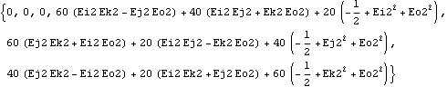 |
If this is not yet sufficiently murky, consider that if the applied moment in the previous example was specified as a constant moment in local coordinates on body 2, the conditions of the moment expressions in local versus global angular coordinates would be reversed. The moment would be a constant in local coordinates and a function of the Euler parameters in global coordinates.
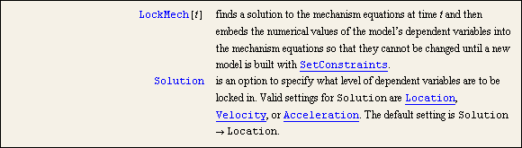
In conclusion, the fastest run times usually result from matching the coordinate system to the types of applied forces and moments on the body. If the applied loads are in global coordinates, use the global coordinate system, and visa versa. 12.5 Locking VariablesThe LockMech function is a special function provided by MechanicalSystems that allows the values of constant dependent variables in a model to be retained to accelerate the evaluation of large models. A special function for locking dependent variables. LockMech replaces the dependent variables in the constraint equations with constant values so that they cannot be changed until the constraints are rebuilt. This function is useful when the model must be solved many times with different applied loads or different inertia properties, all at the same physical configuration. After LockMech has been run, the dependent variables (X2, Y2, ...) in a model are replaced by numeric values so that they no longer need to be replaced at runtime, essentially eliminating the time required to replace them.
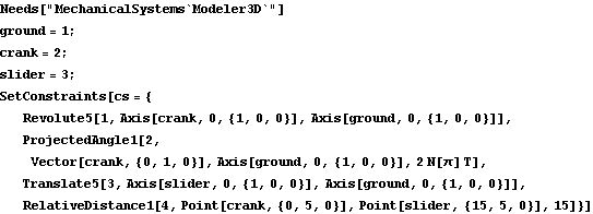
To demonstrate the use of LockMech, the 3D slider-crank model that was used in Section 12.1 is redefined with applied forces. Here is an entire slider-crank model built in one step. And here are the locations of each body at T = 0.1.
Out[6]= | 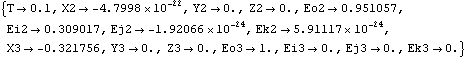 |
We can now add an applied force to the model and solve for the static reaction forces at several values of a parameter that affects the direction of the applied force. A valid location solution pos is passed into SolveMech with the CheckRules -> False option so that regeneration of the location solution does not occur. This applies force to the origin of the slider with constant magnitude and variable direction. Now the model is solved for the static reaction forces at 11 different values of k.
Out[8]= |  |
LockMech is run to embed the location coordinates of the model into all of the equations of motion, including the load vector. The model is solved again for the static reaction forces at 11 different values of k. It is not necessary to use the CheckRules option now because the constraint equations are constant.
Out[11]= |  |
|