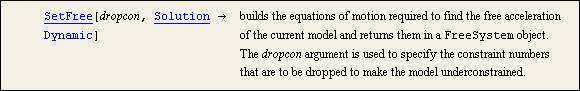
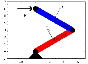
10.3 Free AccelerationThis section covers the use of the SetFree function to build the dynamic equations of motion of an underconstrained model, and the use of the SolveFree function to find the instantaneous free acceleration. To find the time-domain free response of an underconstrained model, the free acceleration is integrated with respect to time. Integration of the equations of motion is covered in Section 10.4. 10.3.1 2D Example MechanismA model of a two-link planar robot arm is developed to demonstrate the use of SetFree and SolveFree to find the instantaneous free acceleration of a mechanism. The robot arm has a force of unit magnitude, but varying direction, applied to the tip of the second link, while the two revolute joints in the arm are free to rotate. By finding the acceleration vector of the tip that results from a 1-unit applied force at a particular configuration of the arm, the "ellipse of mobility" can be plotted.
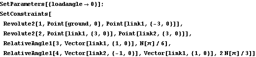
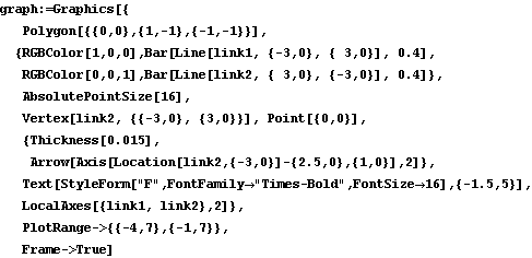
Of the four constraints that make up the robot arm model, two are Revolute2 constraints that model the joints between the ground and link 1, and between link 1 and link 2. The other two RelativeAngle1 constraints are present only to set up the initial position of the arm. They are dropped by SetFree to provide two unconstrained degrees of freedom. The parameter loadangle is used to change the direction of the applied load at the tip of link 2. This loads the Modeler2D package and defines names for each of the body numbers. Here are the constraints, bodies, and loads for the robot arm model. The model is run with the Solution -> Kinematic option so that initial conditions are available for SolveFree. Here is the reaction torque applied by the locked joint between the ground and link 1.
Out[9]= |  |
Here is the robot arm at its initial configuration.
10.3.2 Instantaneous Free AccelerationTo find the free acceleration of an underconstrained mechanism a FreeSystem object is built that contains a new set of equations of motion with one or more constraints dropped from the model. Instantaneous free acceleration. The two RelativeAngle1 constraints are now dropped from the robot arm to give the model two degrees of freedom. If initial conditions are not specified, SetFree takes them from the current default initial guesses LastSolve[]. This drops the constraints that lock the rotation of the joints. This solves the FreeSystem object. Here is the resultant acceleration vector at the tip of link 2.
Out[12]= |  |
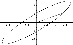
To find the free acceleration corresponding to a sequence of different values of loadangle, SetParameters could be used between each successive run of SolveFree, or the InitialCondition option can be used to pass SolveFree the new parameter values. SolveFree reads all its initial conditions from the InitialCondition option, Parameters[], and the initial conditions contained in the FreeSystem object, in that order. This solves the FreeSystem object at 21 different values of loadangle. Here is a parametric plot of the X and Y components of the resulting acceleration at the tip of link 2. The diagonal line across the plot crosses the ellipse at loadangle = 0.
Out[14]= |  |
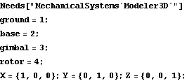
10.3.3 3D Example MechanismThe following mechanism is a simple gyroscope that, dynamically, is not a very simple mechanism. The gyroscope consists of three moving bodies: the base, the gimbal, and the rotor. The base is constrained to rotate about a vertical axis affixed to the ground, while the gimbal rotates about a horizontal axis affixed to the base, and the rotor is constrained to rotate about a fixed axis on the gimbal that is orthogonal to the gimbal's horizontal rotational axis on the base.
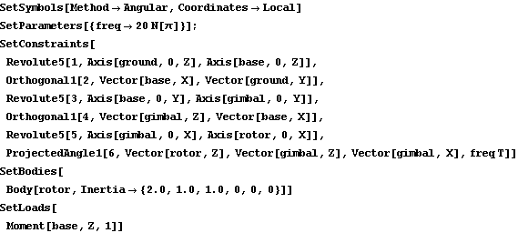
The model is defined so that the origins of each body are always coincident, and so that each body is initially aligned with the global coordinate system, therefore no initial guesses are required because the default initial guesses are exact. The two Orthogonal1 constraints 2 and 4 are present only so that the model can be assembled in a fixed state. They will be dropped to find the free response. A single parameter freq is included in the model to specify the angular speed of the rotor, relative to the gimbal. The gyroscope is modeled in local, angular coordinates so that the angular velocities of interest appear directly in the solution rules.
All of the bodies are massless except the rotor. This makes the results much easier to interpret. The moments of inertia of the rotor are representative of a thin disk.
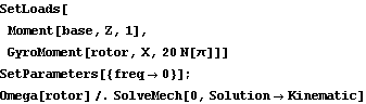
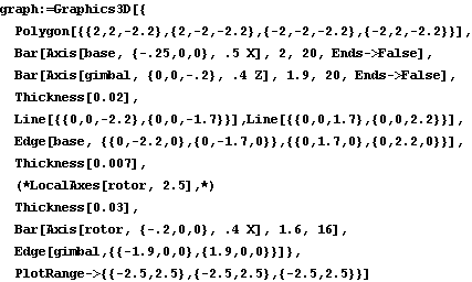
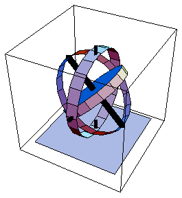
Only one load is applied to the model, a moment applied to the base in the Z direction. Initially this moment has no effect because the base is prevented from rotating by constraint 2. However, when the constraints that prevent the base and gimbal from rotating are dropped, the orthogonal reaction to the moment applied to the base can be observed at the rotor. This loads the Modeler3D package and defines names for each of the body numbers. Here are the constraints, bodies, and loads for the gyroscope model. Here is the gyroscope with the gimbal rotated to make a better picture.
The model is run at T = 0.1 so that initial conditions are available for SolveFree.
Out[26]= |  |
10.3.4 Instantaneous Free AccelerationTo find the free acceleration of the gyroscope, one or more constraints must be dropped. The constraint that prevents rotation of the base, constraint 2, is dropped first. The rotor cannot precess in this state because the gimbal is still locked to the base, but the reaction torques applied to the base that accelerate the rotor can be measured.
No initial conditions are explicitly given. Initial guesses are taken from the default initial guesses that were set by the last run of SolveMech. This drops the constraint that locks the base relative to the ground. This solves the FreeSystem object. The angular acceleration of the rotor is 1.0 in the Z direction. This corresponds to the 1.0 applied moment divided by the 1.0 moment of inertia about the Z axis.
Out[29]= |  |
There is no gyroscopic torque applied to the base by the Revolute5 constraint because the base has zero angular velocity at this instant.
Out[30]= |  |
To make this model a little more interesting, the base is given a nonzero angular velocity with the InitialCondition option for SolveFree. This induces gyroscopic torques in the base constraint. To be consistent with the constraints the Z components of the initial angular velocity of each body must be identical. This solves the FreeSystem object with a new partial initial condition. The rest of the initial conditions are taken from LastSolve[]. The angular acceleration of the rotor now has a component in the Y direction corresponding to the changing direction of the angular velocity vector.
Out[32]= |  |
Now there is a gyroscopic torque applied to the base by the Revolute5 constraint.
Out[33]= |  |
Now the FreeSystem is rebuilt with both the base and the gimbal unlocked. The same initial velocity for the base, gimbal, and rotor is used so that the gyroscope precesses. This builds and solves the FreeSystem object with constraints 2 and 4 dropped. Without the constraint forces applied by constraint 4, the gimbal has an angular acceleration about its Y axis induced by the gyroscopic forces.
Out[36]= |  |
Again, there is no gyroscopic torque applied to the base by the Revolute5 constraint because the gimbal is free to rotate.
Out[37]= |  |
10.3.5 Gyroscopic MomentsGyroscopic forces and moments modeled as per the example in Section 10.3.4 work well for single point analyses. However, if the time-domain free response is desired, such a modeling technique has a serious computational problem. While the rotor is spinning rapidly, the Euler parameters that represent the angular orientation of the rotor are changing sinusoidally and very rapidly. To numerically integrate such a system, the integrator must faithfully track very many periods of the sinusoidal Euler parameters to cover only a few periods of the motion of the more interesting parts of the gyroscope. If the period of the rotor's local rotation is much, much shorter than the period of interest, the integration becomes computationally infeasible.
The way around this problem is to introduce a special forcing function that mimics the gyroscopic torque of a spinning axially symmetric body and apply it to the rotor. This allows the rotor to be rotationally static.
A function to simulate gyroscopic moments. GyroMoment has two important caveats attached to its use: the gyroscopic motion that it models is that of a body rotating about a principal axis of inertia and the two principle moments not associated with the axis of rotation must be equal. For most practical purposes, this means that the body is axially symmetric, and it is rotating about its axis of symmetry.
To demonstrate the use of GyroMoment, the gyroscope model that was presented in Section 10.3.3 is modified to remove the large angular velocity of the rotor and replace it with a GyroMoment load. Here the gyroscopic moment simulation is added to the applied loads, the angular speed of the rotor body is reduced to zero, and the model is run at T = 0 so initial conditions are available to SetFree.
Out[40]= |  |
First, the constraint that locks the base to the ground is dropped and SolveFree is run with the Z direction angular velocity set to 1. The resulting angular velocities and accelerations are missing the large components that were due to the rotation of the rotor.
Out[43]= |  |
But the reaction at the base still reflects the gyroscopic torques.
Out[44]= |  |
This builds and solves the FreeSystem object with constraints 2 and 4 dropped. Without the rotation of the rotor, the angular accelerations of the rotor and gimbal are equal.
Out[47]= |  |
There is still no gyroscopic torque applied to the base when the gimbal is free to rotate.
Out[48]= |  |
The constraint reaction forces that result from using this method are identical to the reaction forces that result from the normal procedure, without the use of GyroMoment. The true values of alpha and omega for the simulated rotor are reproduced by the following calculation. omegalocal is the local angular velocity vector that was passed to GyroMoment. Note that omegatrue and alphatrue match the angular velocity and acceleration components of the rotor in the previous analysis.
Out[50]= |  |
Out[51]= |  |
The equations of motion that are produced by this method are essentially equivalent to the equations of motion without the spinning rotor simulation, with one important difference, these equations of motion can be easily integrated to obtain the time-domain motion of the entire gyroscope assembly without an overwhelming computational burden. Undocumented Graphics Generation
|