Make sure the application is loaded. This is the state-space model of the reactor system considered earlier. | Out[3]= | 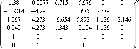 |
The open-loop system has two eigenvalues with positive real parts, and is therefore unstable. | Out[5]= |  |
These are the characteristic value plots for the reactor system. 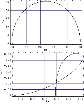
The generalized Nyquist stability theorem requires a net sum of encirclements of the critical point {-1, 0} by the characteristic values equal to the number of unstable poles of the open-loop system. As neither of the characteristic value plots encircles its critical point at {-1, 0}, the closed-loop system with unity negative feedback will be unstable. You can confirm this, by determining the poles of the resulting closed-loop system. This determines the closed-loop system with unity negative feedback. | Out[8]= | 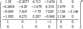 |
These are the closed-loop system poles, with two poles having a positive real part. | Out[10]= |  |
These are the singular value plots of the reactor system. 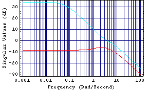
Here, you can see that at the low frequencies these plots are separated by some 42 dB, and at the high frequencies they are separated by some 6 dB. The choice of frequency at which the high-frequency compensator is determined is a compromise. When the high-frequency compensator is determined for  = 5 rad/s, the resulting closed-loop system is unstable, and when it is determined for = 5 rad/s, the resulting closed-loop system is unstable, and when it is determined for  = 10 rad/s, the resulting closed-loop system is stable, but there is still significant interaction. However, when the high-frequency compensator is determined for = 10 rad/s, the resulting closed-loop system is stable, but there is still significant interaction. However, when the high-frequency compensator is determined for  = 30 rad/s, the closed-loop system is stable and there is only a small amount of high-frequency interaction. When even higher frequencies are used in determining the high-frequency compensator, the resulting closed-loop system is stable but the intermediate-frequency interaction increases. = 30 rad/s, the closed-loop system is stable and there is only a small amount of high-frequency interaction. When even higher frequencies are used in determining the high-frequency compensator, the resulting closed-loop system is stable but the intermediate-frequency interaction increases. Here is a high-frequency compensator Kh determined at  = 30 rad/s. = 30 rad/s. | Out[13]= |  |
This applies the compensator to the system. | Out[15]= |  |
The resulting singular value plots show that the largest and the smallest singular values of the system now coincide at frequencies above 20 rad/s, and so the high-frequency interaction has been effectively eliminated. 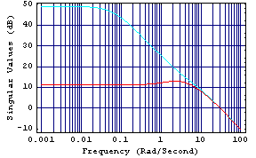
Here are the characteristic loci for the system with this compensator applied. 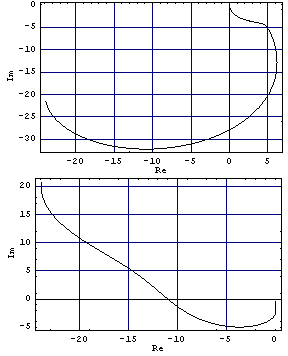
The top plot encircles the critical point at {-1, 0} once in a counterclockwise direction, and likewise the lower plot also encircles the critical point at {-1, 0} once in a counterclockwise direction, as the frequency variable s traces the familiar Nyquist D-contour in the complex plane. Since these plots exhibit two counterclockwise encirclements of the critical points at {-1, 0}, the resulting closed-loop system with unity negative feedback will be stable. However, there is still about a 38-dB gap between the largest and the smallest singular values at the low frequencies. Now, apply two identical PI action single-loop controllers to the system. These compensators have to be identical so that the encirclements by the characteristic loci are not changed. The gain multiplier for the two PI compensators is, here, set equal to 2, to further minimize the intermediate frequency interaction. Here are two identical single-loop compensators. | Out[19]= |  |
This applies the additional compensator to the system. This determines the resulting closed-loop system with unity negative feedback. | Out[22]= |  |
The resulting system is stable with a pair of well-damped dominant complex conjugate poles. | Out[24]= |  |
These are the resulting closed-loop system singular value plots. 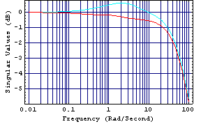
The closed-loop system maximum and minimum singular values are now coincident at the very low frequencies, are almost coincident at the high frequencies, and are close together at the intermediate frequencies. This implies a good reduction in the interaction that was present in the open-loop uncompensated system. Here is a simulation of the closed-loop system. 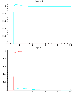
As you can see, the closed-loop system has fast responses with zero steady-state error, and only a small amount of transient interaction from output 1 when a unit step is applied to reference input 2.
You can now compare the overall controller for the reactor system designed using the characteristic locus method with that obtained for the reactor system using the inverse-system Nyquist array approach (see Section 5.2.2). This is the overall forward-path compensator designed using the characteristic locus method. | Out[28]= |  |
|