Before applying any frequency-domain design technique to a multivariable system, you should attempt to find the best individual inputs for controlling the system outputs. Here, the relative gain array is used for that purpose (see Section 5.1). Then one of the frequency-domain compensator design methods implemented in Polynomial Control Systems is applied to construct a simple controller that significantly reduces the interaction present in the system, as demonstrated using the Nyquist array technique (see Section 5.2). At least at zero frequency, the current input-output pairing (the first input controls the first output and the second input controls the second output) appears to be appropriate for the subsequent design. | Out[2]= |  |
Here is the Nyquist array for the system. 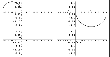
The Nyquist array suggests that the four element Nyquist plots would correspond to stable closed-loop subsystems, if a gain of -1 is applied to element (1, 1) and element (2, 1) before closing the feedback loops with unity negative feedback. This compensator applies a gain of -1 to element (1, 1). | Out[5]= |  |
This is the resulting forward-path transfer-function matrix. | Out[7]= |  |
The Gershgorin circles superimposed on the diagonal elements of the Nyquist array show the interaction present in the system over the bandwidth of interest. 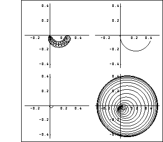
The level of interaction shown by the Gershgorin circles superimposed on element (1, 1) indicates that there will only be a small response from output 2 when a unit-step function is applied to input 1. However, the level of interaction shown for element (2, 2) is not acceptable, and implies that there would be a significant response from output 1 when a unit-step function is applied to input 2. The time responses of this system confirm the interaction predicted by the Nyquist array. These are the resulting variations in the top temperature (solid line) and the bottom temperature (dashed line) for separate unit-step changes in each input. 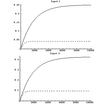
Clearly, a forward-path compensator that would reduce the interaction in loop 2 is needed, and a pseudo-diagonalizing compensator algorithm has been implemented that allows a different frequency value to be applied to each individual column in the resulting system, if desired (see Section 5.2). The compensators determined using this algorithm are always real. This determines a series forward-path constant compensator that will reduce the interaction in loop 2, by applying the pseudo-diagonalizing algorithm to both column 1 and column 2 at zero frequency. | Out[11]= |  |
This connects the compensator in series with the existing forward-path system model. | Out[13]= |  |
This is the resulting Nyquist array plot for the system, using the Gershgorin circles for column dominance. 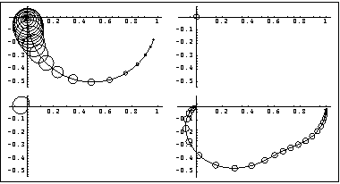
Clearly, the interaction present in loop 2 has been greatly improved over the bandwidth of interest. However, some high-frequency (transient) interaction remains in loop 1. These are the resulting variations in the top temperature (solid lines) and the bottom temperature (dashed lines) for separate changes of one degree C in each system input, which confirm the interaction levels predicted by the Nyquist array. 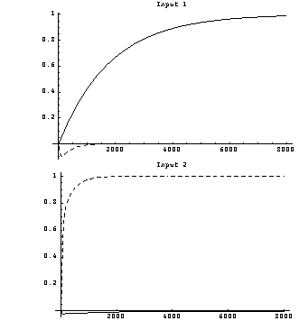
You should note that these time responses are those of the forward-path transfer-function matrix representation of the system; that is, the open-loop plant plus its series compensators. As the interaction in the system has been significantly reduced, you can now add further single-loop tuning compensators, as required, to meet the overall system time response specifications, and close the feedback loops with unity negative feedback. |