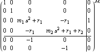
The time domain behavior of the new model objects SystemMatrix, LeftMatrixFraction, and RightMatrixFraction can be obtained using the Control System Professional functions OutputResponse, StateResponse, and SimulationPlot. Make sure the application is loaded. This is a system matrix model of the mass-spring system of Figure 3.1, where two outputs are defined as y1= x1 (the displacement of the mass m1), and y2= x2 (the displacement of the mass m2). | Out[3]= |  |
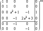
Here is this system matrix model for a given set of parameters. | Out[5]= |  |
This is the symbolic output response of the mass-spring system for a unit step input of force. | Out[7]= |  |
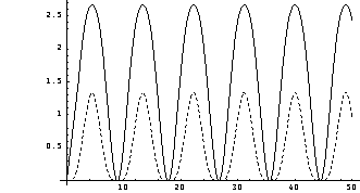
This plots the step response. The solid and dotted lines represent the first and second outputs, respectively. 
As the mass-spring system has no damping, the displacements of the masses m1 and m2 exhibit undamped oscillatory behavior, although these are not pure sinusoids. The smaller amplitude response is that of m2, while the larger amplitude response is the behavior of m1. Consider a multivariable system with two inputs and three outputs. | Out[10]= |  |
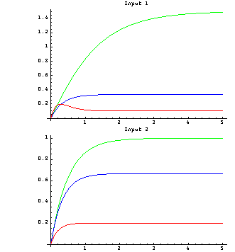
These are the step responses of the system. As usual, SimulationPlot applies the step signal to all inputs in turn. 
The steady-state values of the step responses are as expected from the elements of the corresponding transfer-function matrix. | Out[13]= |  |
|


