- Products & Services
- Technologies
-
Solutions
-
- Engineering, R&D
- Finance, Statistics & Business Analysis
- Education
- Tech & Trends
- Software & Web
- Sciences
- All Solutions »
-
-
Learning & Support
-
- Learning
- Need Help?
- Premium Support
- All Learning & Support »
-
-
Company
-
- Work with Us
- All Company »
-
-
Search
WOLFRAM SYSTEM MODELER
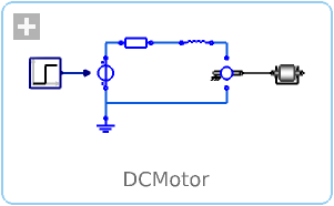
DCMotorDynamic model of a DC motor |
|
Diagram
Wolfram Language
In[1]:=
SystemModel["IntroductoryExamples.MultiDomain.DCMotor"]
Out[1]:=
Information
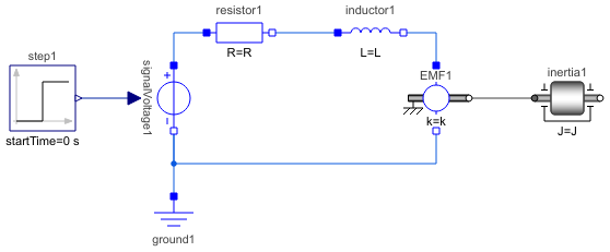
A simple dynamic model of a controlled DC motor consisting of a variable voltage source, a resistor, an inductor, and an electro-motoric force element representing the coupling between electric energy and mechanical energy provided by the magnetic field in the DC motor. The motor axis is represented by a rotating inertia.
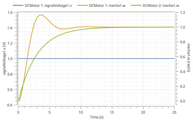
Comparison of step response for the rotational speed of the inertia using the default parameters (DCMotor 1) and with resistance set to 10 Ohm, inductance 0.1 H, and moment of inertia to 0.3 kg m2 (DCMotor 2):
For a step by step tutorial see Multidomain—A Servo Mechanism.
Components (7)
| step1 |
Type: Step Description: Generate step signal of type Real |
|
|---|---|---|
| resistor1 |
Type: Resistor Description: Ideal linear electrical resistor |
|
| inductor1 |
Type: Inductor Description: Ideal linear electrical inductor |
|
| EMF1 |
Type: RotationalEMF Description: Electromotoric force (electric/mechanic transformer) |
|
| ground1 |
Type: Ground Description: Ground node |
|
| signalVoltage1 |
Type: SignalVoltage Description: Generic voltage source using the input signal as source voltage |
|
| inertia1 |
Type: Inertia Description: 1D-rotational component with inertia |
- Services
- Technical Consulting
- Corporate Consulting
- Company
- Events
- About Wolfram
- Careers
- Contact
- Connect
- Wolfram Community
- Wolfram Blog
- Newsletter
© 2024 Wolfram. All rights reserved.