WOLFRAM SYSTEM MODELER
ReadSensorReading analog signals |
|
Diagram
Wolfram Language
In[1]:=
SystemModel["ModelPlug.Examples.ReadSensor"]
Out[1]:=
Information
Hardware Components Used
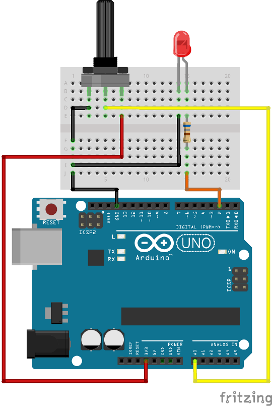
- 1 Arduino board
- 1 LED
- 1 resistor 680 ohms
- 1 potentiometer 100 K
Description
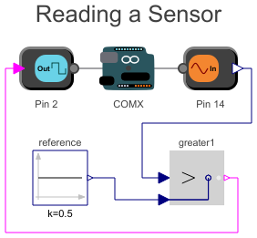
This example shows how to read an analog voltage using the AnalogInput component. The analog signal is then compared to a reference, and if the signal is above the reference, it will turn on an LED. You can see in the following figure how to build this example.
Pin A0 for the Arduino UNO corresponds to pin number 14 for the Firmata. For other boards, the pin numbering may be different. If you have a different board, you can refer to the board capabilities that is printed when the simulation is started to see what pins are mapped to what ports. For the Arduino Lenoardo, A0 is mapped to pin number 18.
Run the simulation and move the potentiometer. You should see that when the position of the shaft is near the middle, the LED changes state.
The AnalogInput component returns a signal between 0 and 1. This value represents the voltage between 0 and the reference voltage. If you prefer to get the signal directly in volts, you need to change the 'MaxValue' property to the reference voltage, but generally it is either 5 V or 3.3 V.
Components (5)
| arduino |
Type: Arduino Description: Component with default configuration for Arduino boards |
|
|---|---|---|
| digitalOutput |
Type: DigitalOutput Description: Writes a digital signal to the specified pin |
|
| analogInput1 |
Type: AnalogInput Description: Reads an analog signal from the specified pin |
|
| greater1 |
Type: Greater Description: Output y is true, if input u1 is greater than input u2 |
|
| reference |
Type: Constant Description: Generate constant signal of type Real |