|
3.2 State-Space Representations
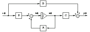
Continuous-time state-space systems (Figure 3.1)
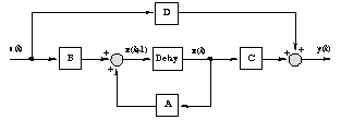
 and discrete-time state-space systems (Figure 3.2)
 are represented by the StateSpace data structure; this guide refers to component matrices using the same symbols,  , ,  , ,  , and , and  . Here . Here  is the state (or evolution) matrix, is the state (or evolution) matrix,  is the input (or control) matrix, is the input (or control) matrix,  is the output (or observation) matrix, and is the output (or observation) matrix, and  is the direct transmission (or feedthrough) matrix. Keeping the same notation for continuous- and discrete-time systems is common in the literature and allows sharing many concepts and algorithms that are essentially identical. (It is also common to use is the direct transmission (or feedthrough) matrix. Keeping the same notation for continuous- and discrete-time systems is common in the literature and allows sharing many concepts and algorithms that are essentially identical. (It is also common to use  , ,  , ,  , and , and  instead of instead of  , ,  , ,  , and , and  for continuous-time systems and for continuous-time systems and  and and  instead of instead of  and and  in the discrete-time case.) in the discrete-time case.)
To distinguish between the two types of systems, the option Sampled is introduced in Section 3.3.

State-space data structure.

Figure 3.1. State-space model of a continuous-time system.

Figure 3.2. State-space model of a discrete-time system.
The StateSpace objects can contain as few as two matrices a and b, but for most functions, at least matrix c and optionally d are required too. If matrices c and d are absent, no assumptions are made about them; if only matrix d is absent, it is routinely assumed to be a zero matrix. The truncated StateSpace[a, b] representation is, of course, of limited value, but contains all the necessary information, for instance, for state feedback regulator design (Section 9.1).
Here is a second-order SISO system with no direct transition term.
In[22]:=
Out[22]=
This is the same system with a zero direct transition term added.
In[23]:=
Out[23]=
The two systems yield the same transfer function and so correspond to the same physical system.
In[24]:=
Out[24]=


Obtaining state-space realizations of transfer functions.
The state-space representation can be obtained directly from the differential equations of the system (difference equations in the case of a discrete-time system) or from the transfer matrix. In the latter case, the target form of the state-space model can be specified by the option TargetForm, with the default value ControllableCompanion that corresponds to the controllable companion form, constructed by inspection. The adopted definition of the controllable companion form is due to, for example, Gopal (1993). (In the literature, this form is sometimes referred to as the controllable canonical form.) For the strictly proper transfer matrix
 of size  , where , where  are of that size as well, are of that size as well,  and and  being the number of inputs and outputs, respectively, the controllable companion realization is assumed to be being the number of inputs and outputs, respectively, the controllable companion realization is assumed to be
 where  and and  are zero and identity matrices of size are zero and identity matrices of size  and the matrix and the matrix  is zero. The dimension of the system is is zero. The dimension of the system is  . If the transfer matrix . If the transfer matrix  is proper (but not strictly proper), the same representation of the strictly proper part of is proper (but not strictly proper), the same representation of the strictly proper part of  holds while the matrix holds while the matrix  can be found as can be found as
 Similarly, the observable companion realization is
 where  and and  are zero and the identity matrices of size are zero and the identity matrices of size  and the dimension of the system is and the dimension of the system is  . This form can be obtained using the option TargetForm . This form can be obtained using the option TargetForm  ObservableCompanion. Note that the controllable and observable companion forms may not be of minimal order and, as a rule, are ill-conditioned. Chapter 8 describes the methods to transform the model further. ObservableCompanion. Note that the controllable and observable companion forms may not be of minimal order and, as a rule, are ill-conditioned. Chapter 8 describes the methods to transform the model further.
Here is a transfer function.
In[25]:=
Out[25]=
This produces the controllable companion realization.
In[26]:=
Out[26]=
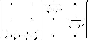
The structure of the state-space system is more transparent with the use of TraditionalForm (Section 3.4). Clearly, this is not the minimal-order model.
In[27]:=
Out[27]//TraditionalForm=
This reduces the order of the system using the function MinimalRealization described in Section 8.1. To obtain a simpler result, we assert that none of the symbolic variables are complex.
In[28]:=
Out[28]//TraditionalForm=
This produces the observable companion realization.
In[29]:=
Out[29]//TraditionalForm=
It is easy to demonstrate that both realizations correspond to the initial system.
In[30]:=
Out[30]=
By itself, StateSpace does not check the consistency of component matrices; however, the consistency is the prerequisite for many other functions to operate in a meaningful way. Consistency here means that matrix a must be square,  , where , where  is the number of states; matrix b must be is the number of states; matrix b must be  , where , where  is the number of inputs; matrix c must be is the number of inputs; matrix c must be  , where , where  is the number of outputs; and matrix d, if used, must be is the number of outputs; and matrix d, if used, must be  . When entering state-space objects manually, these requirements should be kept in mind. The function ConsistentQ checks that they are satisfied. . When entering state-space objects manually, these requirements should be kept in mind. The function ConsistentQ checks that they are satisfied.
StateSpace, as well as other control objects, accepts options, which could, if so desired, come wrapped in lists. Therefore, caution should be exercised to not confuse an empty list of options with an empty matrix in a control object's description. For this reason, parsing an empty list as a valid list of options is disallowed for all control objects as well as in other functions in Control System Professional where this may cause a confusion.
|