|
9.1.1 Ackermann's Formula
According to Ackermann's formula, the feedback matrix K that places the poles of a single-input system  into the positions into the positions  can be found as can be found as
 where

is the unit vector of length  , ,

is the controllability matrix, and

is the characteristic polynomial of matrix  . Here . Here  is the identity matrix, and the coefficients is the identity matrix, and the coefficients  are such that are such that  , ,  , ,  , ,  are the roots of the polynomial: are the roots of the polynomial:

The function StateFeedbackGains with the option Method  Ackermann implements this algorithm. Ackermann implements this algorithm.

State feedback design using Ackermann's formula.
The Ackermann method, besides being useful for single-input systems, may also find application if an attempt is to be made to control a multi-input system through a single input. The option ControlInput  Automatic is used in such cases to find the "best" control using the condition number of the corresponding controllability matrix as a criterion. It is also possible to specify the control input explicitly. Automatic is used in such cases to find the "best" control using the condition number of the corresponding controllability matrix as a criterion. It is also possible to specify the control input explicitly.

Option specific to the Ackermann method.

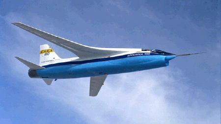
Figure 9.2. F-8 aircraft in flight. Photograph by Dryden Flight Research Center, NASA.
As an example we consider an approximate model of the lateral dynamics of an F-8 aircraft (Figure 9.2) linearized about a particular set of flight conditions and reproduced after Brogan (1991). The state and input vectors in the model are

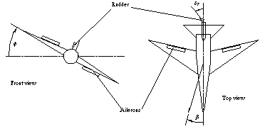
where  , ,  , ,  , and , and  are the roll and yaw rates and the sideslip and roll angles, respectively, and are the roll and yaw rates and the sideslip and roll angles, respectively, and  and and  are the aileron and rudder deflections. Figure 9.3 introduces the nomenclature. are the aileron and rudder deflections. Figure 9.3 introduces the nomenclature.

Figure 9.3. Aircraft schematic.
This is the state-space model of the aircraft.
In[15]:=
Out[15]=
Here are the closed-loop poles we wish the system to have.
In[16]:=
StateFeedbackGains may be asked to determine whether it is possible to control the aircraft using only one of the inputs if, say, a malfunction prevents manipulation of the other. If such input exists, the feedback gain matrix will contain a nonzero row corresponding to this input.
StateFeedbackGains finds that the system is better controlled through the second input (i.e., the rudder deflection) and returns the corresponding feedback gains.
In[17]:=
Out[17]=
The attempt to control the aircraft from only the first input fails, and we are presented with messages suggesting that the trouble possibly stems from the system being uncontrollable.
In[18]:=


Out[18]=
Indeed, the system is not controllable from its first input; in other words, the aircraft cannot be controlled by only the aileron deflections (at least not within the linearized model).
In[19]:=
Out[19]=
|