8.3.2 Damping ExampleTo demonstrate the application of damping to a Mech model, a 2D model of a simple four-bar linkage is developed. The model consists of three moving bodies: the drive bar, the driven bar, and the center bar. The kinematic input to the model is the rotation of the drive bar.
Damping is first applied to the model at a point on the center bar that traces out an eccentric path in the 2D plane. Coulombic friction is then applied to the rotational axis of the drive bar. This loads the Modeler2D package. Here is the four-bar mechanism, with a moving point locus.
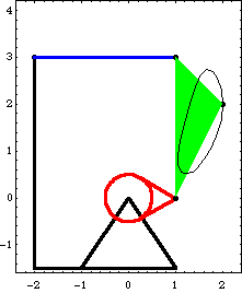
BodiesFour body objects are required for the four-bar model. Each bar is attached to another bar at its local origin and at a point at the other end of the bar on the local X or Y axis. Names are defined for each of the body numbers in the model. Here are the body objects for the four-bar model. The body properties are incorporated into the current model. ConstraintsFive constraints, one of which is a driving constraint, are required to model the four-bar mechanism. A RotationLock1 constraint is used as a driving constraint to rotate the drive bar. Four Revolute2 constraints model the four pivot points in the four-bar mechanism. Here are the constraint objects for the four-bar model. The constraints are incorporated into the current model. Damping LoadA damping force is applied to point 2 on the center bar relative to the ground. The direction of the frictional force opposes the global velocity of point 2, and the coefficient of damping is 5.0. Here is a damping load. The load is incorporated into the current model. RuntimeBecause of the presence of T in the driving constraint cs[1], the model can be run through its intended range of motion by varying T directly with the SolveMech command. The numerical value of T specifies the angle of rotation of the drive bar in revolutions. Now run the model at T = 0.3.
Out[26]= |  |
Here is the four-bar model at T = 0.3.
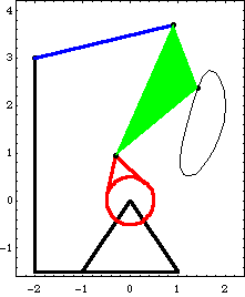
Because the loading in this model is dependent on velocity terms, the Solution -> Kinematic option must be used with SolveMech to solve for the reaction forces. If Solution -> Static were used, SolveMech would assume that all velocities were zero, thus, the applied damping would have zero magnitude and zero reactions would result. Here is the solution, including the generalized reaction forces.
Out[27]= |  |
The reaction moment at the rotational driver is the moment required to rotate the drive bar.
Out[28]= |  |
Here is the reaction force at the drive bar axis.
Out[29]= |  |
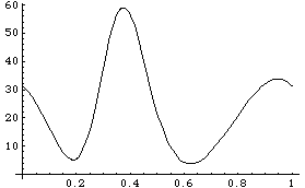
PlotsTo generate a plot of the torque required to turn the drive bar, the four-bar model is run from T = 0 to T = 1 in 21 steps, a full turn of the drive bar, while requesting that SolveMech interpolate the results. This generates an interpolated solution set and returns one part of the solution.
Out[30]= |  |
Here is an explicit expression for the drive torque.
Out[31]= |  |
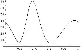
Here is a plot of the drive torque as a function of time.
Out[32]= |  |
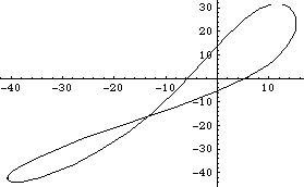
A parametric plot of the x-y reaction at the axis of the drive bar can be easily created. The plot ranges only from T = 0 to T = 0.95 so the start and end points are apparent. Here is the drive arm axis reaction vector.
Out[33]= |  |
Here is a parametric plot of the drive arm axis reaction vector.
Out[34]= |  |
Friction LoadA very simple Coulombic friction load is applied to the rotational axis of the drive bar, with respect to the ground. The load is a pure moment resisting the direction of motion, the magnitude of which is proportional to the magnitude of the reaction vector at the drive bar axis. A coefficient of friction of 0.5 is assumed and is applied to a journal bearing with radius 0.4. Here is a simple Coulombic friction load. The load is added to the current model. More PlotsThis generates another interpolated solution set. The drive torque function that was developed earlier can be plotted again with the new solution rules. Note that the required drive torque is slightly higher. Here is a plot of the drive torque with friction at the drivebar axis.
Out[38]= |  |
|