Control an RLC Circuit Modeled as a Descriptor System
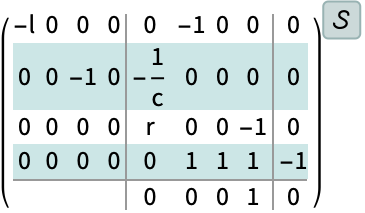
This resistor-inductor-capacitor circuit can easily be modeled from the component equations using a descriptor state-space model.
In[1]:=1
✖
https://wolfram.com/xid/0b2vwdudoocgm8rew5xo1subtp47wgtmqop2l1ej409jaoeo32-5umy70
In[3]:=3
✖
https://wolfram.com/xid/0b2vwdudoocgm8rew5xo1subtp47wgtmqop2l1ej409jaoeo32-riadh4
Out[3]=3

In[4]:=4
✖
https://wolfram.com/xid/0b2vwdudoocgm8rew5xo1subtp47wgtmqop2l1ej409jaoeo32-zou3c
In[5]:=5
✖
https://wolfram.com/xid/0b2vwdudoocgm8rew5xo1subtp47wgtmqop2l1ej409jaoeo32-vbdwp
Out[6]=6

In[7]:=7
✖
https://wolfram.com/xid/0b2vwdudoocgm8rew5xo1subtp47wgtmqop2l1ej409jaoeo32-eq83d4
In[9]:=9
✖
https://wolfram.com/xid/0b2vwdudoocgm8rew5xo1subtp47wgtmqop2l1ej409jaoeo32-t44uvw
Out[9]=9
In[10]:=10
✖
https://wolfram.com/xid/0b2vwdudoocgm8rew5xo1subtp47wgtmqop2l1ej409jaoeo32-6d36w8
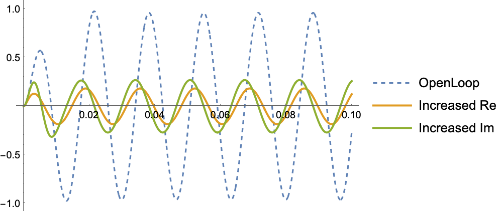
Moving the poles either further to the left or away from the real axis decreases the magnitude response:
In[12]:=12
✖
https://wolfram.com/xid/0b2vwdudoocgm8rew5xo1subtp47wgtmqop2l1ej409jaoeo32-bs1n0e
Out[12]=12
