|
2.2.6 The Observer Design
Any state-feedback design requires knowledge of state variables. Thus it is necessary to estimate the state variables (design an observer) using the inputs, measured outputs, and the system matrices. The first step in designing an observer is to determine whether the system is observable. This is accomplished by using the function ObserverHessenbergForm.
This is the observer-Hessenberg form of the system.
In[35]:=
Out[35]=
Since the superdiagonal blocks of the observer-Hessenberg form are nonsingular, the system is observable.
In[36]:=
Out[36]=
The outputs of the system permit direct measurement of the first two state variables. For the remaining three states, a reduced-order estimator of order three is constructed. To satisfactorily track system performance, the poles of the state estimator are chosen to be faster than those of the system.
This is a suitable set of poles of the estimator.
In[37]:=
The reduced-order state estimator of order three is constructed using the block version of the recursive bidiagonal scheme.
In[38]:=
In[39]:=
Out[39]//NumberForm=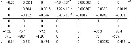
The observer is connected to the system according to the block diagram in Figure 6.1. An implementation of the general approach, shown in Figure 2.1, includes a dummy identity block I that allows construction of the closed-loop system using only the elementary interconnecting functions.
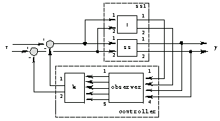
Figure 2.1. The reduced-order estimator in the feedback loop.
The system has two inputs.
In[40]:=
Out[40]=
This connects the all-pass block in parallel to the system ss.
In[41]:=
Out[41]=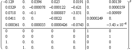
The controller consists of the serially connected observer and the feedback gains block.
In[42]:=
In[43]:=
Out[43]//NumberForm=
This closes the feedback loop and deletes the outputs of the dummy system.
In[44]:=
The eigenvalues of the combined system are the union of the eigenvalues of the closed-loop system and the state estimator. This property is known as separation property.
The separation property is verified.
In[45]:=
Out[45]=
Finally, compare the performance of closed-loop systems that use exact and approximated knowledge of the state variables. The approximation is obtained by the reduced-order state estimator.
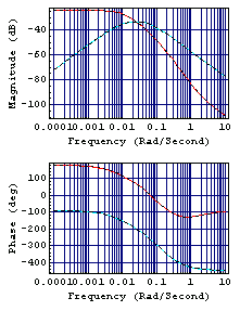
This is the Bode plot for the second input of the closed-loop systems. The exact and reduced-order designs are represented as solid and dashed lines, correspondingly. The systems possess comparable frequency responses.
In[46]:=
This chooses the random initial conditions.
In[47]:=
These are the output responses of the open-loop system for the input signal defined in Section 2.2.2 and the aforementioned initial conditions.
In[48]:=
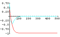
These are the output responses of the closed-loop system with the exact (solid lines) and reduced-order state estimator (dashed lines) control law designs.
In[49]:=
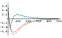
These plots show that the responses obtained by using exact states and estimated states match closely as time increases (that is, as  approaches infinity). approaches infinity).
|