|
GPS Satellites
http://www.wolfram.com/applications/astronomer/index.html
setup
<<Astronomer`HomeSite`

SetLocation[GeoLongitude 145. Degree, 145. Degree,
GeoLatitude -37.8 Degree, -37.8 Degree,
TimeZone 11]; 11];
Global-Positioning-System (GPS) Network
The GPS (Global-Positioning-System) is a set of 24 satellites scattered all over the sky. With an appropriate hand-held device the GPS network allows a user to determine their precise position on the surface of the Earth to very high accuracy.
Two levels of service are provided. A Standard Positioning Service (SPS), and a Precise Positioning Service (PPS) for military applications.
SPS provides horizontal accuracy to within 100 meters, vertical accuracy to within 140 meters, and timing accuracy to within 340 nanoseconds. The military PPS is much more accurate.
The GPS satellites are not in geo-stationary orbit, but instead orbit twice every time the Earth rotates once. This means that for any observer the satellites appear to orbit once overhead each day. Such an arrangement gives better coverage. It is also clever in the sense that the motion of any GPS satellite will repeat itself each day.
The GPS constellation of 24 satellites are arranged in six different orbital planes, each inclined 55 degrees to the equator. To obtain exactly two orbits per day, the satellites are placed at an altitude of 20,200km.
Orbital Elements
Here are the orbital elements for the satellites in the GPS network.
**WARNING** orbital elements can change over time, as the manouevering thrusters can be fired on a satellite to keep it in a useful orbit. The following elements are valid for November, 1995, but will hopefully be accurate for a long while after that.
SetOrbitalElements[GPS$BII01,"1 19802U 89013A 95309.78625012 .00000044 00000-0 10000-3 0 1374","2 19802 55.2415 119.5676 0024903 166.8993 193.2646 2.00558765 49214"];
SetOrbitalElements[GPS$BII02,"1 20061U 89044A 95310.12425691 -.00000070 00000-0 10000-3 0 1356","2 20061 54.3389 295.6341 0148690 216.2913 142.6807 2.00562578 46963"];
SetOrbitalElements[GPS$BII03,"1 20185U 89064A 95309.46269993 .00000048 00000-0 10000-3 0 1568","2 20185 54.9918 120.0554 0018021 345.1903 14.7678 2.00563410 45528"];
SetOrbitalElements[GPS$BII04,"1 20302U 89085A 95311.99487820 -.00000028 00000-0 10000-3 0 1507","2 20302 53.3022 235.5298 0012602 161.9154 198.1821 2.00560752 44371"];
SetOrbitalElements[GPS$BII05,"1 20361U 89097A 95309.51292439 -.00000067 00000-0 10000-3 0 9893","2 20361 55.8630 62.1773 0083168 127.4522 233.2874 2.00562872 33801"];
SetOrbitalElements[GPS$BII06,"1 20452U 90008A 95308.91159786 .00000047 00000-0 10000-3 0 942","2 20452 54.0203 175.9353 0060424 84.9203 275.8640 2.00555253 42290"];
SetOrbitalElements[GPS$BII07,"1 20533U 90025A 95309.81575630 -.00000068 00000-0 10000-3 0 1137","2 20533 54.7055 296.3210 0046396 76.8590 283.6440 2.00571962 41089"];
SetOrbitalElements[GPS$BII08,"1 20724U 90068A 95310.63692876 .00000031 00000-0 10000-3 0 9632","2 20724 54.8909 117.6456 0123375 175.0948 185.0026 2.00565690 36966"];
SetOrbitalElements[GPS$BII09,"1 20830U 90088A 95311.68333574 -.00000063 00000-0 10000-3 0 9743","2 20830 55.7976 60.0713 0066825 100.7914 259.9499 2.00558523 37625"];
SetOrbitalElements[GPS$BIIA10,"1 20959U 90103A 95308.59702208 .00000057 00000-0 10000-3 0 9352","2 20959 55.0867 119.7418 0101671 230.6740 128.4520 2.00569333 36155"];
SetOrbitalElements[GPS$BIIA11,"1 21552U 91047A 95309.36722733 -.00000073 00000-0 10000-6 0 9083","2 21552 56.0805 57.9003 0067614 243.5332 115.7608 2.00556318 31766"];
SetOrbitalElements[GPS$BIIA12,"1 21890U 92009A 95309.82631890 -.00000048 00000-0 10000-3 0 7189","2 21890 53.8716 235.8883 0055833 186.8785 173.0393 2.00566300 27148"];
SetOrbitalElements[GPS$BIIA13,"1 21930U 92019A 95312.02868255 -.00000081 00000-0 10000-3 0 7073","2 21930 55.7176 357.5043 0035955 177.6774 182.4030 2.00560713 26113"];
SetOrbitalElements[GPS$BIIA14,"1 22014U 92039A 95309.57534888 .00000049 00000-0 00000+0 0 6018","2 22014 54.8410 177.5465 0090120 319.6589 39.8163 2.00565192 17908"];
SetOrbitalElements[GPS$BIIA15,"1 22108U 92058A 95311.03326852 -.00000037 00000-0 10000-3 0 6526","2 22108 54.0960 236.6603 0116512 153.2147 207.3878 2.00554789 23116"];
SetOrbitalElements[GPS$BIIA16,"1 22231U 92079A 95311.71578651 .00000045 00000-0 10000-3 0 6198","2 22231 54.6798 178.6446 0034883 287.9804 71.7292 2.00558969 21703"];
SetOrbitalElements[GPS$BIIA17,"1 22275U 92089A 95310.86718541 .00000051 00000-0 10000-3 0 6474","2 22275 54.6302 176.1719 0041196 251.7793 107.8746 2.00569775 21093"];
SetOrbitalElements[GPS$BIIA18,"1 22446U 93007A 95308.94096534 -.00000065 00000-0 10000-3 0 6311","2 22446 54.3516 296.5342 0084700 352.8776 7.0001 2.00570243 20049"];
SetOrbitalElements[GPS$BIIA19,"1 22581U 93017A 95311.07789310 -.00000081 00000-0 10000-3 0 4755","2 22581 55.2186 357.0327 0057641 35.6787 324.7672 2.00569133 19148"];
SetOrbitalElements[GPS$BIIA20,"1 22657U 93032A 95311.21472538 -.00000081 00000-0 10000-3 0 5473","2 22657 55.2328 356.8734 0073557 213.1497 146.4480 2.00558867 14473"];
SetOrbitalElements[GPS$BIIA21,"1 22700U 93042A 95310.18087022 -.00000046 00000-0 10000-3 0 4681","2 22700 54.2701 237.4755 0042226 349.5004 10.4338 2.00568538 17257"];
SetOrbitalElements[GPS$BIIA22,"1 22779U 93054A 95309.77286643 -.00000069 00000-0 10000-3 0 5331","2 22779 54.4938 296.5435 0019878 254.4897 105.2778 2.00554177 16006"];
SetOrbitalElements[GPS$BIIA23,"1 22877U 93068A 95311.31668252 -.00000068 00000-0 10000-3 0 3414","2 22877 55.5221 58.0628 0026823 301.6012 58.1308 2.00568348 14928"];
SetOrbitalElements[GPS$BIIA24,"1 23027U 94016A 95308.40802999 -.00000085 00000-0 10000-3 0 2777","2 23027 55.0710 359.0020 0066423 200.6511 159.1230 2.00565178 12175"];
Here is a list of all the satellites in the network. Orbital elements for these are defined in the cell above.
GPSnetwork =
{GPS$BII01, GPS$BII02, GPS$BII03,
GPS$BII04, GPS$BII05, GPS$BII06,
GPS$BII07, GPS$BII08, GPS$BII09,
GPS$BIIA10,GPS$BIIA11,GPS$BIIA12,
GPS$BIIA13,GPS$BIIA14,GPS$BIIA15,
GPS$BIIA16,GPS$BIIA17,GPS$BIIA18,
GPS$BIIA19,GPS$BIIA20,GPS$BIIA21,
GPS$BIIA22,GPS$BIIA23,GPS$BIIA24};
The orbit of one of the GPS satellites can be displayed, for a given 24 hour period, as follows:
OrbitTrackPlot[GPS$BII01, {1995,11,4},
PlotPoints 100]; 100];
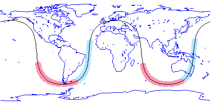
Note the orbit roughly repeats itself after 24 hours. The precise geographic position of the satellite at midnight on the given date is:
GetLocation[GPS$BII01, {1995,11,4,0,0,0}]

You can plot the current position of all the GPS satellites on the surface of the Earth at some given time using:
PlanetPlot[Earth, {1995,11,4,0,0,0},
Epilog  {RGBColor[1,0,0], {RGBColor[1,0,0],
PointSize[0.01],
Point[{GeoLongitude,
GeoLatitude}/Degree] /.
(GetLocation[#1,
{1995,11,4,0,0,0}]&)
/@ GPSnetwork}];
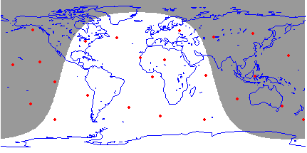
In the above, the red dots represent the position of a GPS satellite. Note that as the hours go by the satellites move around the globe, and return to roughly the same points after 24 hours.
The above graphic shows the position of the satellites as seen from the sky looking down on the Earth. You can equally display the positions as seen from the Earth looking out into the sky. For example:
StarChart[{{0,360},{-90,90}},
MagnitudeRange 3, 3,
MagnitudeScale 0.4, 0.4,
Epilog {RGBColor[1,0,0], {RGBColor[1,0,0],
(OrbitMark[#1, {1995,11,4}]&)
/@GPSnetwork}];
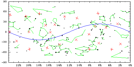
The red crosses, mark the current position of each GPS satellite.
Six orbital planes
As stated earlier the 24 GPS satellites orbit in only six different planes each tilted 55 degrees to the equator. You can see this by plotting the full orbit track of each satellite to see only six different tracks.
StarChart[{{0,360},{-90,90}},
{1995,11,4},
MagnitudeRange 3, 3,
MagnitudeScale 0.4, 0.4,
Epilog {RGBColor[1,0,0], {RGBColor[1,0,0],
(OrbitTrack[#1, {1995,11,4},
{1995,11,5}]&)
/@ GPSnetwork}];
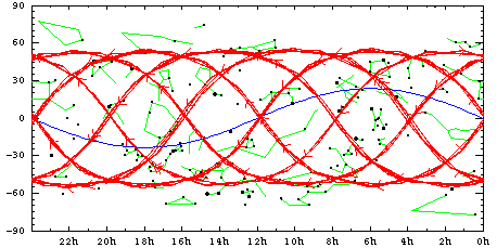
The six different planes are organized as follows:
Satellites 05, 09, 11, 23 cross at an ascension of 04 hours.
Satellites 01, 03, 08, 10 cross at an ascension of 08 hours.
Satellites 06, 14, 16, 17 cross at an ascension of 12 hours.
Satellites 04, 12, 15, 21 cross at an ascension of 16 hours.
Satellites 02, 07, 18, 22 cross at an ascension of 20 hours.
Satellites 13, 19, 20, 24 cross at an ascension of 00 hours.
To make it clearer that there are just six orbital planes, you can plot all 24 orbits using the OrbitPlot command.
OrbitPlot[GPSnetwork, {1995,11,5},
Distance 30000*KiloMeter]; 30000*KiloMeter];
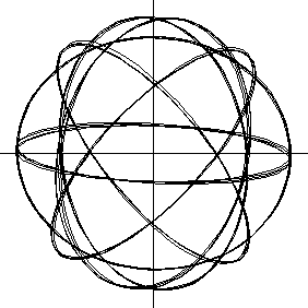
Only six distinct orbits are visible in the above graphic, and they are arranged symmetrically. You can plot the orbits in 3D space, but the symmetry becomes less clear.
OrbitPlot3D[{GPS$BII05,GPS$BII01,
GPS$BII06,GPS$BII04,
GPS$BII02,GPS$BIIA13},
{1995,11,5},
Distance 30000*KiloMeter, 30000*KiloMeter,
PlotStyle {RGBColor[1,0,0], {RGBColor[1,0,0],
RGBColor[1,1,0],
RGBColor[0,1,0],
RGBColor[0,1,1],
RGBColor[0,0,1],
RGBColor[1,0,1]},
PlotRegion {{-0.4,1.4},{-0.4,1.4}}, {{-0.4,1.4},{-0.4,1.4}},
Background GrayLevel[0.7], GrayLevel[0.7],
SphericalRegion True]; True];
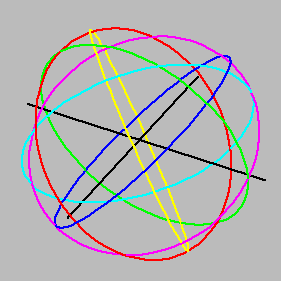
Stereographic 3D plot
The symmetry becomes a little clearer if you produce a stereographic pair of 3D images. By crossing your eyes you can then see the orbits in full 3D.
viewit[view_] := OrbitPlot3D[
{GPS$BII05,GPS$BII01,
GPS$BII06,GPS$BII04,
GPS$BII02,GPS$BIIA13},
{1995,11,5},
Distance 30000*KiloMeter, 30000*KiloMeter,
PlotStyle {RGBColor[1,0,0], {RGBColor[1,0,0],
RGBColor[1,1,0],
RGBColor[0,1,0],
RGBColor[0,1,1],
RGBColor[0,0,1],
RGBColor[1,0,1]},
PlotRegion {{-0.4,1.4},{-0.4,1.4}}, {{-0.4,1.4},{-0.4,1.4}},
ViewPoint view, view,
Background GrayLevel[0.7], GrayLevel[0.7],
SphericalRegion True, True,
DisplayFunction Identity] Identity]
p1=viewit[{1.3,-2.40,2.0}];
p2=viewit[{1.4,-2.35,2.0}];
Show[GraphicsArray[{p1,p2},
GraphicsSpacing 0], 0],
DisplayFunction $DisplayFunction]; $DisplayFunction];
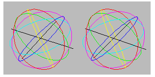
Converge your eyes to see above image in full 3D
If you can cross your eyes successfully you will see clearly that the red, green and blue orbits are at right angles to each other. Similarly for the cyan, magenta and yellow orbits. The two systems are inclined in some complicated way.
Animation of network
Because the GPS satellites move roughly back to their original position after 24 hours, you can make a nice animation of the entire network. Here we use ZenithStarChart to show the position of the satellites overhead (as seen from the current location, which is Melbourne Australia) in half hour intervals.
Do[ZenithStarChart[{1995,11,4,h,0,0},
MagnitudeRange -10, -10,
RotateLabel False, False,
Ecliptic False, False,
Constellations False, False,
Planets None, None,
Epilog {RGBColor[1,0,0], {RGBColor[1,0,0],
(OrbitMark[#1,
{1995,11,4,h,0,0},
ViewPoint TopoCentric]&) TopoCentric]&)
/@ GPSnetwork}],
{h,0,23.9,0.5}]
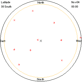
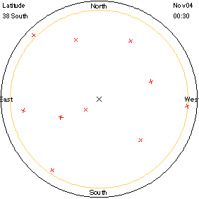
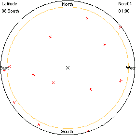
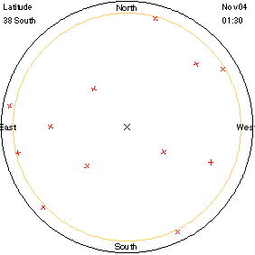
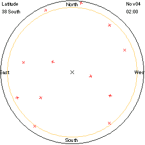
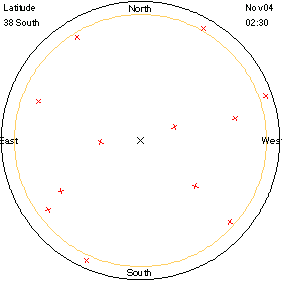
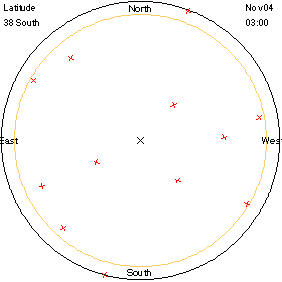
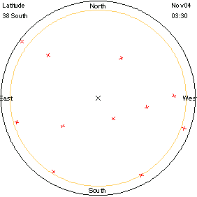
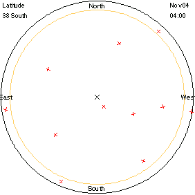
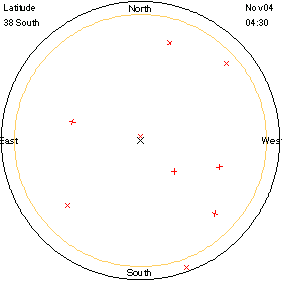
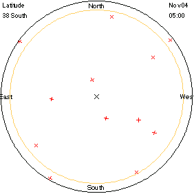
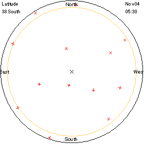
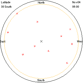
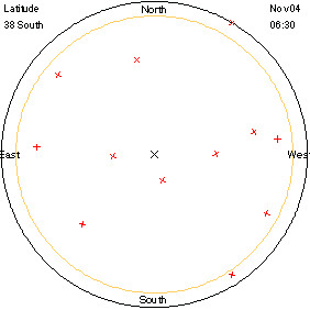
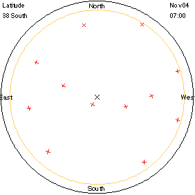
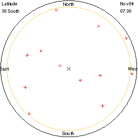
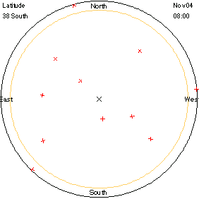
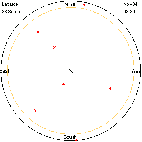
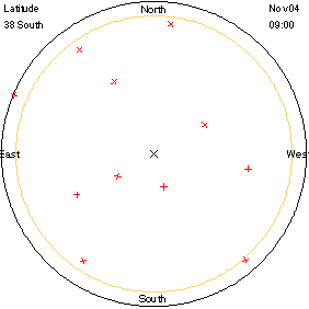
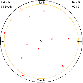
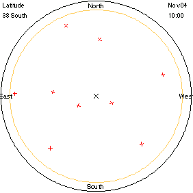
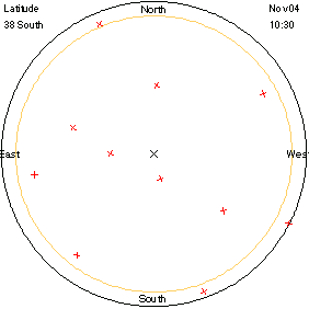
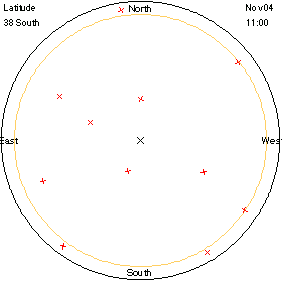
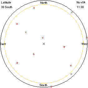
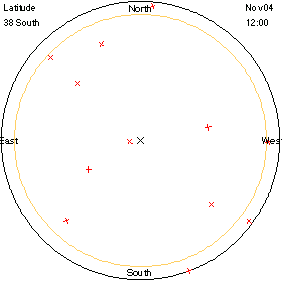
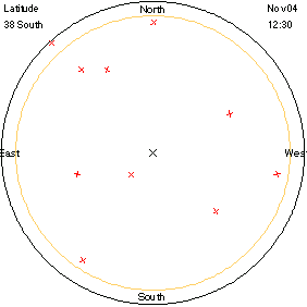
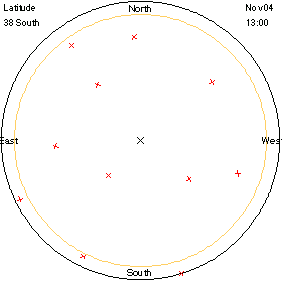
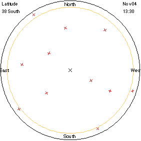
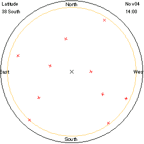
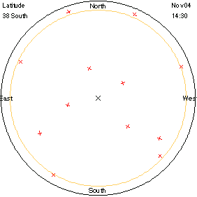
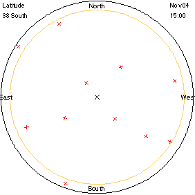
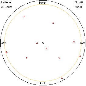
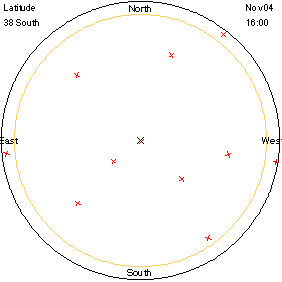
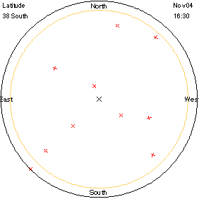
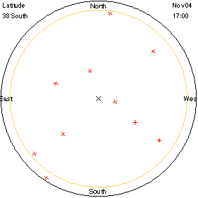
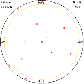
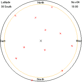
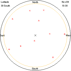
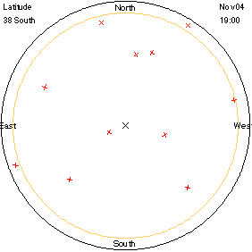
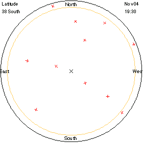
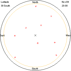
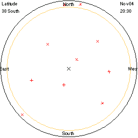
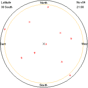
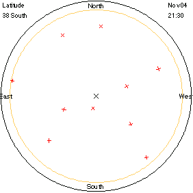
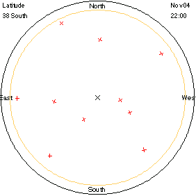
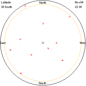
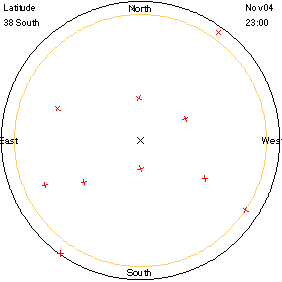
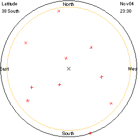
Note that at any given time there are always several GPS satellites high up in the sky near the zenith point marked with a black cross. The satellites themselves are marked with red crosses.
When the above is animated it is possible to make out fixed curves. By writing a function using the HorizonCoordinates command, it is possible to compute the shape of those curves and then use them in a ZenithStarChart plot. Thus let
daytrack[sat_] :=
Line[Block[{az, alt, h},
Table[{az, alt} =
N[{Azimuth, Altitude/Degree} /.
HorizonCoordinates[sat,
{1995,11,4,h,0,0},
ViewPoint -> TopoCentric]];
If[alt < 0, Null,
(90 - alt)*{-Sin[az], Cos[az]}],
{h, 0, 24.1, 0.5}]]]
then the day-tracks of all the GPS satellites can be plotted as follows:
ZenithStarChart[{1995,11,4,0,0,0},
MagnitudeRange -10, -10,
RotateLabel False, False,
Ecliptic False, False,
Constellations False, False,
Planets None, None,
Epilog {RGBColor[1,0,0], {RGBColor[1,0,0],
daytrack /@ GPSnetwork}];
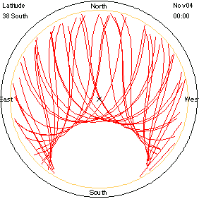
No GPS satellite can pass near a Celestial Pole. And because the viewing location is in the Southern hemisphere then we expect a region around the South Celestial Pole to be vacant, and the above plot clearly shows that.
Another Animation of network
Similary the motion of the satellites over the surface of the Earth could also be animated.
Do[PlanetPlot[Earth, {1995,11,4,h,0,0},
Shading -> False,
Epilog ->
{RGBColor[1, 0, 0], PointSize[0.01],
Point[{GeoLongitude,
GeoLatitude}/Degree] /.
(GetLocation[#1,
{1995,11,4,h,0,0}] & ) /@
GPSnetwork}],
{h, 0, 23.9, 0.5}]
Visible Satellites
There are many low orbit Earth satellites that are visible to the naked-eye.
See the Mir.nb notebook for more details on how to spot a satellite.
The Mir Space Station is the best and brightest object to see. It can appear as bright as the brightest stars. A Space Shuttle can also appear as bright as Mir, but missions are not common.
Other satellites that can be bright are: the Hubble Space Telescope (HST), the Upper Atmosphere Research Satellite (UARS), and the Cosmic Background Explorer (COBE).
Orbital Elements
Here are the orbital elements for some of the brighter naked-eye visible satellites.
**WARNING** orbital elements can change over time, as the manouevering thrusters can be fired on a satellite to keep it in a useful orbit. The following elements are valid for November, 1995, but will hopefully be accurate for a long while after that.
SetOrbitalElements[Mir,"1 16609U 86017A 95310.84681701 .00004957 00000-0 71549-4 0 3075" "2 16609 51.6465 163.1993 0003914 297.2823 62.7378 15.57955220555192"];
SetOrbitalElements[COBE,"1 20322U 89089 A 95142.98467641 -.00000127 00000-0 -80986-4 0 1224","2 20322 98.9618 159.4007 0009846 47.0580 313.1429 14.03444026282057"];
SetOrbitalElements[UARS,"1 21701U 91063B 95307.42457078 -.00000054 00000-0 16355-4 0 7151" "2 21701 56.9812 298.6928 0005326 106.5647 253.5963 14.96447668226416"];
SetOrbitalElements[HST,"1 20580U 90037B 95311.08286752 .00000512 00000-0 35492-4 0 7343","2 20580 28.4704 212.5666 0006228 358.9627 1.0947 14.90966576105255"];
SetOrbitalElements[STS73,"1 23688U 95056A 95303.25000000 -.00001724 54492-5 00000+0 0 410","2 23688 39.0124 50.5515 0007898 340.2406 106.4468 16.03225100 1550"];
Mir Space Station Complex (MIR, 16609/1986-17A)
Mir is in an orbit 340km up and tilted 51.6 degrees to the equator. It was launched from Tyuratam on 1986 February 19. Mir appears very bright at around magnitude 0, but can reach magnitude -1, and flashes of around magnitude -3 have been known to occur.
Space Shuttle (STS)
Space Shuttle missions (usually referred to by labels such as STS-71, where STS stands for Space Transportation System) are typically launched into orbits a few hundred kilometers up and tilted at maybe 28 degrees to the equator. Missions to the Mir Space Station are tilted higher at 51.7 degrees. A Space Shuttle can appear very bright at around magnitude 0 or better.
Hubble Space Telescope (HST, 20580/1990-037B)
The Hubble Space Telescope (HST) is in an orbit 580km up and tilted 28.5 degrees to the equator. It was launched from a Space Shuttle on 1990 February 6.
Upper Atmospheric Research Satellite (UARS, 21701/1991-63B)
The Upper Atmosphere Research Satellite (UARS) is in an orbit 570km up and tilted 57.0 degrees to the equator. It was launched from the Space Shuttle Discovery (STS-48 mission) on 1991 September 12.
Cosmic Background Explorer (COBE, 20322/1989-89A)
The Cosmic Background Explorer (COBE) is in an orbit 880km up and tilted 99.0 degrees to the equator (i.e a polar orbit). It was launched from the Vandenberg Air Force Base on 1989 November 18. COBE appears bright at magnitudes between +1 and +3.
Other Satellites
There are many thousands of satellites orbiting Earth.
Current Orbital Elements for them all are available on the Internet. The best site is http://www.celestrak.com/NORAD/elements/index.html and the elements are kept in Two-Line-Element format.
The site contains current elements for visible, weather, television, geo-stationary and GPS satellites etc.
You can feed the Two-Line-Elements directly into the SetOrbitalElements function as shown in the earlier sections.
|