|
3.10.5 WriteModel

Command structure of WriteModel.
The function WriteModel converts a DAEObject dae into a behavioral model for a given simulator. An interface can be defined which connects the model with a circuit. The connections are then given by a list of rules of the form:
  -> Voltage[ -> Voltage[ , ,  ], ],
 -> Current[ -> Current[ , ,  ], ],
 -> Voltage[ -> Voltage[ , ,  ], ],
 -> Current[ -> Current[ , ,  ] ]
This interface definition will generate two input port branches from  to to  (voltage) and from (voltage) and from  to to  (current) and two output branches from (current) and two output branches from  to to  (voltage) and from (voltage) and from  to to  (current). (current).
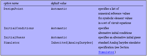
WriteModel has the following options:

Options for WriteModel.
Options Description
A detailed description of all WriteModel options is given below in alphabetical order:
DesignPoint
With DesignPoint -> { -> ->  , ,  } you can overwrite the design point given in the DAEObject (see also CircuitEquations in Section 3.5.1). The default setting is DesignPoint -> Automatic, which means to use the design point given in the DAEObject. } you can overwrite the design point given in the DAEObject (see also CircuitEquations in Section 3.5.1). The default setting is DesignPoint -> Automatic, which means to use the design point given in the DAEObject.
InitialConditions
The option InitialConditions allows for explicitly specifying initial conditions. The default setting is InitialConditions -> Automatic, which means to use the initial conditions given in the DAEObject. Valid option values are as follows:

Values for the InitialConditions option.
InitialGuess
The option InitialGuess allows for explicitly specifying an initial guess for the Newton iteration when computing the operating point. The default setting is InitialGuess -> Automatic, which means to use the initial guess given in the DAEObject. Possible option values are as follows:

Values for the InitialGuess option.
Simulator
The following simulator-dependent modeling languages are supported:

Simulators and model types supported by WriteModel.
Examples
Load Analog Insydes.
In[1]:= <<AnalogInsydes`
Read a netlist.
In[2]:= net = ReadNetlist[
"AnalogInsydes/DemoFiles/Multivibrator.cir",
Simulator -> "PSpice"]
Out[2]= 
Set up a system of equations.
In[3]:= dae = CircuitEquations[net,
ElementValues -> Symbolic, AnalysisMode -> DC]
Out[3]= 
Display the variables of dae. These variables can be used as outputs.
In[4]:= GetVariables[dae]
Out[4]= 
Display the parameters of dae. These parameters can be used as inputs.
In[5]:= GetParameters[dae]
Out[5]= 
Generate the Saber MAST model test. The first branch ("IP" -> "IN") defines IC as the corresponding input current. The second branch ("VP" -> "VN") defines an input voltage VCC and an output current I$VCC.
In[6]:= WriteModel["test.sin", "test", dae,
{"IP", "IN", "VP", "VN"},
{IC -> Current["IP", "IN"], VCC -> Voltage["VP", "VN"],
I$VCC -> Current["VP", "VN"]},
Simulator -> "Saber"]
|