|
3.5.1 CircuitEquations

Command structure of CircuitEquations.
The first argument of CircuitEquations must be a Circuit or Netlist object. If it is not a flat netlist, then ExpandSubcircuits will be called first automatically to expand any subcircuit or device model references. CircuitEquations sets up modified nodal, sparse tableau, or extended sparse tableau equations for AC, DC, or transient analysis. CircuitEquations returns a DAEObject.
The type and appearance of equations generated with CircuitEquations can be changed with the following options:
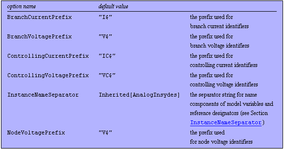
Naming convention options for CircuitEquations.
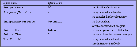
Analysis mode specific options for CircuitEquations.
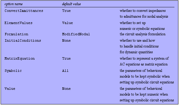
Equation-formulation options for CircuitEquations.
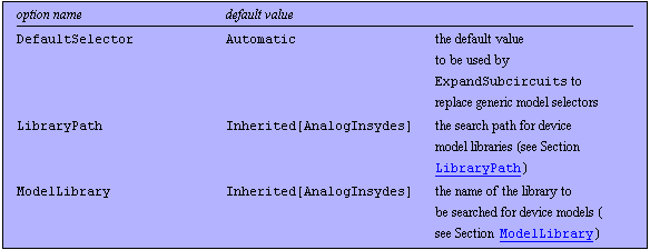
Model library options for CircuitEquations.

Miscellaneous options for CircuitEquations.
See also: Netlist, Circuit, ExpandSubcircuits, Chapter 4.3.
Options Description
A detailed description of all CircuitEquations options is given below in alphabetical order:
AnalysisMode
The option AnalysisMode -> mode specifies the circuit analysis mode for which CircuitEquations sets up a system of equations. Possible values are:

Values for the AnalysisMode option.
With the setting AnalysisMode -> AC, CircuitEquations sets up a system of small-signal Laplace-domain equations. CircuitEquations does not linearize nonlinear circuits. Therefore, the first argument of CircuitEquations must represent a linear circuit. If it contains references to device models, the AC equivalent circuits of the referenced device are used to set up the equations. By default, AC equations are set up in matrix formulation, but this can be changed using the MatrixEquation option (see below).
With the setting AnalysisMode -> DC, CircuitEquations yields a system of (usually nonlinear) DC equations. Any time derivatives resulting from the constitutive equations of dynamic elements as well as derivatives with respect to other independent quantities are set to zero.
With AnalysisMode -> Transient, you can set up a system of differential-algebraic equations (DAE) for nonlinear dynamic circuits. The independent variable of transient analysis is given by the value of the option IndependentVariable, which is not necessarily time.
BranchCurrentPrefix
With BranchCurrentPrefix -> "string", you can specify the prefix string CircuitEquations prepends to an element's reference designator to generate a unique branch current identifier.
For example, with BranchCurrentPrefix -> "I$", the current through a resistor R1 will be named I$R1.
 BranchVoltagePrefix
With BranchVoltagePrefix -> "string", you can specify the prefix string CircuitEquations prepends to an element's reference designator to generate a unique branch voltage identifier.
For example, with BranchVoltagePrefix -> "V$", the voltage across a resistor R1 will be named V$R1.
 ControllingCurrentPrefix
With ControllingCurrentPrefix -> "string", you can specify the prefix string CircuitEquations prepends to the reference designator of a current-controlled source to generate a unique identifier for the controlling current.
For example, with ControllingCurrentPrefix -> "IC$", the controlling current of a current-controlled voltage source CV1 will be named IC$CV1.
 ControllingVoltagePrefix
With ControllingVoltagePrefix -> "string", you can specify the prefix string CircuitEquations prepends to the reference designator of a voltage-controlled source to generate a unique identifier for the controlling voltage.
For example, with ControllingVoltagePrefix -> "VC$", the controlling voltage of a voltage-controlled voltage source VV1 will be named VC$VV1.
 ConvertImmittances
With the option ConvertImmittances, you can control the way in which CircuitEquations handles impedances when setting up modified nodal equations. The following values are allowed:

Values for the ConvertImmittances option.
For example, with ConvertImmittances -> True, a resistance R1 will appear as an admittance 1/R1 in a system of modified nodal equations. With ConvertImmittances -> False, the resistance will not be converted to an admittance, and the MNA equations will be augmented by the branch current I$R1.
 DefaultSelector
With the option DefaultSelector, you can specify the key used by ExpandSubcircuits to replace the right-hand sides of generic device model selector specifications in netlists generated with ReadNetlist. The setting DefaultSelector -> selector causes all generic selectors to be replaced by the key selector. Generic selector specifications have the form
Selector -> Selector["device", "type", "instance"]
for example,
Selector -> Selector["BJT", "Q2N2222", "Q1"]
Possible values are:

Values for the DefaultSelector option.
The standard setting DefaultSelector -> Automatic causes the default selector to be determined from the value of the option AnalysisMode. This enables ExpandSubcircuits to load semiconductor device models from the model library which are compatible with the current analysis mode.
DesignPoint
The DesignPoint option allows you to specify a set of numerical reference values for the circuit parameters in a symbolic system of circuit equations. It allows the following values:

Values for the DesignPoint option.
The design point is stored in the DAEObject returned by CircuitEquations. If available, design-point information is applied automatically whenever numerical calculations are performed with a system of equations which has been set up with ElementValues -> Symbolic. The design point can be extracted from the DAEObject with the function GetDesignPoint.
ElementValues
With ElementValues -> value, you can decide whether CircuitEquations sets up a system of circuit equations symbolically or numerically. Possible choices are:

Values for the ElementValues option.
With the settings ElementValues -> Symbolic and DesignPoint -> Automatic, CircuitEquations will extract design-point information from a netlist automatically. The design point is stored in the DAEObject returned by CircuitEquations. It can be retrieved with GetDesignPoint.
Formulation
The option Formulation -> type selects the type of circuit equations set up by CircuitEquations and allows the following values:

Values for the Formulation option.
Modified nodal analysis expresses systems of circuit equations in terms of node voltages and currents through impedance branches.
Sparse tableau analysis yields systems of circuit equations in terms of all branch currents and branch voltages.
In addition to the branch currents and voltages, extended sparse tableau analysis also includes all node voltages of a circuit.
 FrequencyVariable
With FrequencyVariable -> symbol, you can change the symbol CircuitEquations uses to denote the complex frequency in AC equations. The default setting is FrequencyVariable -> s.
IgnoreMissingGround
IgnoreMissingGround is an option needed for analyzing pure control circuits (also known as block diagrams). Equation setup for control circuits is based on the modified nodal analysis functionality for electrical circuits, which are expected to contain a ground node. CircuitEquations displays an error message when you try to set up equations from a netlist in which no reference to the ground node is present. As pure control networks do not have ground nodes, these error messages must be suppressed by means of the IgnoreMissingGround option, which allows the following values:

Values for the IgnoreMissingGround option.
 IndependentVariable
With IndependentVariable -> var, you can specify a variable other than time as independent variable for transient analysis.
Note that in Analog Insydes, transient analysis does not necessarily mean analysis in the time domain. You can perform transient analysis, i.e. solving differential-algebraic equations, with respect to any other independent variable, for instance, temperature. This feature is useful for tasks such as parametric analyses or sizing problems with differential-algebraic constraints. Possible values for the IndependentVariable option are:

Values for the IndependentVariable option.
If AnalysisMode -> Transient, then time-dependent variables or derivatives of circuit variables with respect to time or other quantities are handled as follows.
 InitialConditions
The option InitialConditions allows you to specify how CircuitEquations handles initial conditions for dynamic quantities, such as capacitor voltages and inductor currents. The following values are allowed:

Values for the InitialConditions option.
InitialTime
With InitialTime ->  , you can specify the point of time for which initial conditions are given. By default, , you can specify the point of time for which initial conditions are given. By default,  , but you may choose any other value. , but you may choose any other value.
NodeVoltagePrefix
With NodeVoltagePrefix -> "string" you can specify the prefix string CircuitEquations prepends to a node name to generate a node voltage identifier.
For example, with NodeVoltagePrefix -> "V$", the node voltage at node 1 will be named V$1.
 Protocol
This option describes the standard Analog Insydes protocol specification (see Section 3.14.5). The top-level function for the Protocol option is CircuitEquations. The second-level function is ExpandSubcircuits. Protocol output generated by models is printed as third level.
Symbolic
The Symbolic option gives you control over the set of symbolic parameters of behavioral models which are kept as symbolic quantities in a system of circuit equations. The Symbolic option is the complement of the Value option and expects the following values:

Values for the Symbolic option.
If the value form {instances -> params,  } is chosen, both instances and params can be a string pattern or a list of string patterns. The instances specification may have the following format: } is chosen, both instances and params can be a string pattern or a list of string patterns. The instances specification may have the following format:

Format specifications for instances.
The params specification may have the following format:

Format specifications for params.
 TimeVariable
With the option TimeVariable -> var, you can change the symbol which CircuitEquations uses to denote time. By default, this symbol is used to denote the independent variable in transient analysis. In addition, all explicit references to the identifier Time are replaced by the time variable.
Value
The Value option gives you control over the set of symbolic parameters of behavioral models which are kept as numeric quantities in a system of circuit equations. The Value option is the complement of the Symbolic option.

Values for the Value option.
If the value form {instances -> params,  } is chosen, both instances and params can be a string pattern or a list of string patterns. The instances specification may have the following format: } is chosen, both instances and params can be a string pattern or a list of string patterns. The instances specification may have the following format:

Format specifications for instances.
The params specification may have the following format:

Format specifications for params.
 Examples
Load Analog Insydes.
In[1]:= <<AnalogInsydes`
This defines an RLC lowpass filter circuit.
In[2]:= rlcf = Netlist[
{V1, {1, 0}, V},
{R1, {1, 2}, R},
{L1, {2, 3}, L},
{C1, {3, 0}, C}
]
Out[2]= 
Set up a system of AC equations.
In[3]:= CircuitEquations[rlcf, AnalysisMode -> AC] // DisplayForm
Out[3]//DisplayForm= 
Set up a system of DC equations.
In[4]:= CircuitEquations[rlcf, AnalysisMode -> DC] // DisplayForm
Out[4]//DisplayForm= 
Set up a system of time-domain equations.
In[5]:= CircuitEquations[rlcf,
AnalysisMode -> Transient] // DisplayForm
Out[5]//DisplayForm= 
Change the branch current prefix to "ib$".
In[6]:= CircuitEquations[rlcf,
BranchCurrentPrefix -> "ib$"] // DisplayForm
Out[6]//DisplayForm= 
Change the branch voltage prefix to "ub$".
In[7]:= CircuitEquations[rlcf, Formulation -> SparseTableau,
BranchVoltagePrefix -> "ub$"] // DisplayForm
Out[7]//DisplayForm= 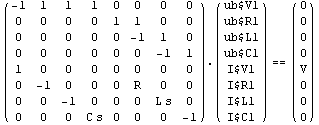
Do not convert R and L to equivalent admittances.
In[8]:= CircuitEquations[rlcf,
ConvertImmittances -> False] // DisplayForm
Out[8]//DisplayForm= 
The DefaultSelector option allows you to choose a different set of device models than would be normally used for the selected analysis mode. You can use this feature to set up circuit equations for noise analysis. Noise equations are essentially AC equations with some extensions, that can be included by selecting noise models instead of plain AC models using DefaultSelector -> Noise.
Read in a PSpice netlist and small-signal data.
In[9]:= buffer = ReadNetlist[
"AnalogInsydes/DemoFiles/Buffer.cir",
"AnalogInsydes/DemoFiles/Buffer.out",
Simulator -> "PSpice"]
Out[9]= 
Set up a system of AC equations.
In[10]:= CircuitEquations[buffer, AnalysisMode -> AC,
Protocol -> {None, Notebook}]


Out[10]= 
Set up a system of AC equations with noise extensions.
In[11]:= CircuitEquations[buffer, AnalysisMode -> AC,
DefaultSelector -> Noise, Protocol -> {None, Notebook}]


Out[11]= 
Specify numerical reference values for the circuit parameters.
In[12]:= eqs = CircuitEquations[rlcf, DesignPoint -> {V -> 1.,
R -> 1000., L -> 0.001, C -> 2.2*10^-6}]
Out[12]= 
Retrieve design point from DAEObject.
In[13]:= GetDesignPoint[eqs]
Out[13]= 
Define an RLC lowpass filter circuit with design-point information.
In[14]:= rlcf2 = Netlist[
{V1, {1, 0}, Symbolic -> V, Value -> 1.},
{R1, {1, 2}, Symbolic -> R, Value -> 1000.},
{L1, {2, 3}, Symbolic -> L, Value -> 0.001},
{C1, {3, 0}, Symbolic -> C, Value -> 2.2*10^-6}
]
Out[14]= 
Set up a system of AC equations with numerical coefficients.
In[15]:= CircuitEquations[rlcf2,
ElementValues -> Value] // DisplayForm
Out[15]//DisplayForm= 
Set up a symbolic system of AC equations.
In[16]:= eqssym = CircuitEquations[rlcf2,
ElementValues -> Symbolic]
Out[16]= 
Show the equations.
In[17]:= eqssym // DisplayForm
Out[17]//DisplayForm= 
Get the design point from the DAEObject.
In[18]:= GetDesignPoint[eqssym]
Out[18]= 
Set up a system of sparse tableau equations.
In[19]:= CircuitEquations[rlcf,
Formulation -> SparseTableau] // DisplayForm
Out[19]//DisplayForm= 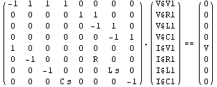
Set up a system of extended sparse tableau equations.
In[20]:= CircuitEquations[rlcf,
Formulation -> ExtendedTableau] // DisplayForm
Out[20]//DisplayForm= 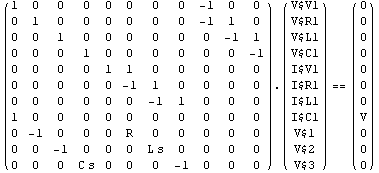
The default setting for the complex frequency is FrequencyVariable -> s, which is the most widely used symbol. However, some people prefer to use the setting FrequencyVariable -> p.
Use the symbol p to denote the complex frequency.
In[21]:= CircuitEquations[rlcf,
FrequencyVariable -> p] // DisplayForm
Out[21]//DisplayForm= 
This defines a simple control circuit with a signal source, a forward signal path, and a feedback path.
In[22]:= fbloop = Netlist[
{HS1, {in}, X[Frequency]},
{HG1, {in, out}, Hf[Frequency]},
{HG2, {out, in}, Hfb[Frequency]}
]
Out[22]= 
By default, CircuitEquations prints a warning because the netlist does not contain a reference to the electrical ground node 0. To turn off the warning, you must set IgnoreMissingGround -> True.
Set up modified nodal equations for the control circuit.
In[23]:= CircuitEquations[fbloop, NodeVoltagePrefix -> "x$"]


Out[23]= 
This tells Analog Insydes to ignore the missing reference to ground.
In[24]:= fbleqs = CircuitEquations[fbloop,
IgnoreMissingGround -> True, NodeVoltagePrefix -> "x$"];
fbleqs // DisplayForm
Out[25]//DisplayForm= 
This defines a circuit with two time-varying and temperature-dependent resistors.
In[25]:= tempckt = Netlist[
{V1, {1, 0}, V1},
{R1, {1, 2}, R1[Time]*(1 + TC11*TEMP)},
{R2, {2, 0}, R2[Time]*(1 + TC12*TEMP)},
{C1, {2, 0}, C1}
]
Out[26]= 
By default, TEMP is simply regarded as a global parameter. Equations for transient analysis are formulated with time as independent variable.
Set up circuit equations for time-domain analysis.
In[26]:= CircuitEquations[tempckt,
AnalysisMode -> Transient] // DisplayForm
Out[27]//DisplayForm= 
Now we use TEMP as independent variable. This causes the time derivative due to C1 to be set to zero and Time to be replaced by the value of InitialTime.
Designate temperature as independent variable.
In[27]:= CircuitEquations[tempckt, AnalysisMode -> Transient,
IndependentVariable -> TEMP] // DisplayForm
Out[28]//DisplayForm= 
This assigns an initial condition to the inductor L1.
In[28]:= rlcfic = Netlist[
{V1, {1, 0}, V},
{R1, {1, 2}, R},
{L1, {2, 3}, Value -> L, InitialCondition -> iL0},
{C1, {3, 0}, C}
]
Out[29]= 
By default, initial conditions are ignored by CircuitEquations. To use the given initial conditions, you must specify InitialConditions -> Automatic or InitialConditions -> All.
Set up circuit equations for transient analysis.
In[29]:= CircuitEquations[rlcfic,
AnalysisMode -> Transient] // DisplayForm
Out[30]//DisplayForm= 
Use initial conditions only where specified explicitly.
In[30]:= CircuitEquations[rlcfic, AnalysisMode -> Transient,
InitialConditions -> Automatic] // DisplayForm
Out[31]//DisplayForm= 
Use given initial conditions, set all other initial conditions to zero.
In[31]:= CircuitEquations[rlcfic, AnalysisMode -> Transient,
InitialConditions -> All] // DisplayForm
Out[32]//DisplayForm= 
Use the symbol t0 to denote the initial time.
In[32]:= CircuitEquations[rlcfic, AnalysisMode -> Transient,
InitialConditions -> All, InitialTime -> t0
] // DisplayForm
Out[33]//DisplayForm= 
Change the node voltage prefix to "vn$".
In[33]:= CircuitEquations[rlcf,
NodeVoltagePrefix -> "vn$"] // DisplayForm
Out[34]//DisplayForm= 
With the default settings Symbolic -> All and Value -> None, all device parameters of the diode appear in symbolic form when you set up a system of circuit equations with ElementValues -> Symbolic.
This defines a simple half-wave diode rectifier circuit.
In[34]:= rectifier = Netlist[
{V1, {1, 0}, Symbolic -> Vin,
Value -> 5*Sin[2*Pi*50*Time]},
{D1, {1 -> A, 2 -> C}, Model -> "Diode",
Selector -> Selector["Diode", "Spice", "D1"]},
{RL, {2, 0}, Symbolic -> RL, Value -> 1000.0},
{CL, {2, 0}, Symbolic -> CL, Value -> 2.2*^-5}
]
Out[35]= 
Set up symbolic circuit equations for transient analysis.
In[35]:= CircuitEquations[rectifier, AnalysisMode -> Transient,
ElementValues -> Symbolic] // DisplayForm
Out[36]//DisplayForm= 
You can also tell CircuitEquations to treat all device parameters as numeric quantities.
Replace all parameters in device model equations by numerical values.
In[36]:= CircuitEquations[rectifier, AnalysisMode -> Transient,
ElementValues -> Symbolic, Symbolic -> None
] // DisplayForm
Out[37]//DisplayForm= 
Finally, the Symbolic option allows you to specify for each device or group of devices the parameters which CircuitEquations should keep in symbolic form.
Keep only the parameters AREA and TEMP of all diode instances "D*" in symbolic form, replace all other model parameters by numerical values.
In[37]:= CircuitEquations[rectifier,
AnalysisMode -> Transient, ElementValues -> Symbolic,
Symbolic -> {"D*" -> {AREA, TEMP}}] // DisplayForm
Out[38]//DisplayForm= 
Use the symbol  to denote time. to denote time.
In[38]:= CircuitEquations[tempckt, AnalysisMode -> Transient,
TimeVariable -> \[Tau]] // DisplayForm
Out[39]//DisplayForm= 
With the default settings Symbolic -> All and Value -> None, all device parameters of the diode appear in symbolic form when you set up a system of circuit equations with ElementValues -> Symbolic.
Set up a system of symbolic circuit equations for transient analysis.
In[39]:= CircuitEquations[rectifier, AnalysisMode -> Transient,
ElementValues -> Symbolic] // DisplayForm
Out[40]//DisplayForm= 
You can also tell CircuitEquations to treat all device parameters as numeric quantities.
Replace all parameters in device model equations by numerical values.
In[40]:= CircuitEquations[rectifier, AnalysisMode -> Transient,
ElementValues -> Symbolic, Value -> All] // DisplayForm
Out[41]//DisplayForm= 
Finally, the Value option allows you to specify for each device or group of devices the parameters which CircuitEquations should treat as numeric quantities.
Replace the parameters TEMP, TNOM, $k, and $q of the model instance D1 by their numerical values.
In[41]:= CircuitEquations[rectifier,
AnalysisMode -> Transient, ElementValues -> Symbolic,
Value -> {"D1" -> {TEMP, TNOM, $k, $q}}] // DisplayForm
Out[42]//DisplayForm= 
|