|
2.7.2 Analysis of a Differential Amplifier
Transient Analysis
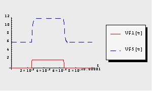
In this section, we want to examine a more complicated circuit to demonstrate the features and capabilities of the DAE solver. Consider the differential amplifier circuit shown in Figure 7.2 consisting of four bipolar junction transistors. We shall compute the transient response  to a rectangular voltage pulse applied at node 1. to a rectangular voltage pulse applied at node 1.
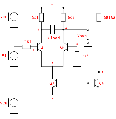
Figure 7.2: Differential amplifier circuit
Again we start by writing a netlist (of course we could have used ReadNetlist as well). Let the values of the circuit elements be given as  , ,  , ,  , and , and  . The supply voltages are . The supply voltages are  and and  . For all transistors Q1, . For all transistors Q1,  , Q4, we use the full Gummel-Poon transistor model implemented in the Analog Insydes model library (see Section 4.3.2). We assume the following model parameter values: transport saturation current , Q4, we use the full Gummel-Poon transistor model implemented in the Analog Insydes model library (see Section 4.3.2). We assume the following model parameter values: transport saturation current  , large-signal forward and reverse current gains , large-signal forward and reverse current gains  and and  , and the global temperature , and the global temperature  . .
In[10]:= diffAmp =
Circuit[
Netlist[
{RS1, {1, 2}, Symbolic -> RS1, Value -> 1.*10^3},
{RS2, {3, 0}, Symbolic -> RS2, Value -> 1.*10^3},
{RC1, {4, 8}, Symbolic -> RC1, Value -> 1.*10^4},
{RC2, {5, 8}, Symbolic -> RC2, Value -> 1.*10^4},
{RBIAS, {7, 8}, Symbolic -> RBIAS, Value -> 2.*10^4},
{CLOAD, {4, 5},
Symbolic -> CLOAD, Value -> 5.*10^-12},
{Q1, {4 -> C, 2 -> B, 6 -> E}, Model -> BJT,
Selector -> GummelPoon, Parameters -> BJTNPN},
{Q2, {5 -> C, 3 -> B, 6 -> E}, Model -> BJT,
Selector -> GummelPoon, Parameters -> BJTNPN},
{Q3, {6 -> C, 7 -> B, 9 -> E}, Model -> BJT,
Selector -> GummelPoon, Parameters -> BJTNPN},
{Q4, {7 -> C, 7 -> B, 9 -> E}, Model -> BJT,
Selector -> GummelPoon, Parameters -> BJTNPN},
{VCC, {8, 0}, Type -> VoltageSource,
Symbolic -> VCC, Value -> 12.},
{VEE, {9, 0}, Symbolic -> VEE, Value -> -12.},
{V1, {1, 0}, V1}
],
ModelParameters[Name -> BJTNPN, Type -> "NPN",
BF -> 255.9, BR -> 6.092, IS -> 14.34*10^-15],
GlobalParameters[TEMP -> 300.15]
]
Out[11]= 
Setting up the circuit equations in the time-domain yields the following DAE system of 32 equations in 32 variables.
In[11]:= diffAmpMNA = CircuitEquations[diffAmp,
AnalysisMode -> Transient]
Out[12]= 
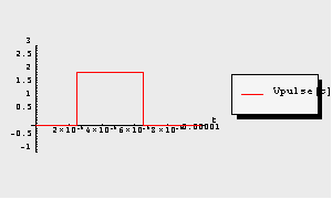
Next, we define the input signal  . We choose a rectangular voltage pulse with an amplitude of . We choose a rectangular voltage pulse with an amplitude of  , a duration of , a duration of  and a delay of and a delay of  . This waveform can be set by the Analog Insydes command PulseWave. . This waveform can be set by the Analog Insydes command PulseWave.
In[12]:= Vpulse[t_] :=
PulseWave[t, 0, 2, 2.5*10^-6, 0, 0, 4.*10^-6, 10^-5]
A graphical representation of the stimulus signal is shown below.
In[13]:= TransientPlot[Vpulse[t], {t, 0., 10^-5},
PlotRange -> {-1, 3}]
Out[14]= 
Then, we call NDAESolve to simulate the transient behavior of the differential amplifier for  . The NonlinearMethod option allows for choosing between different algorithms for solving systems of nonlinear algebraic equations numerically. By default, Mathematica's numerical solver FindRoot is applied, whereas in this example we want to make use of another implementation of Newton's method called NewtonIteration. . The NonlinearMethod option allows for choosing between different algorithms for solving systems of nonlinear algebraic equations numerically. By default, Mathematica's numerical solver FindRoot is applied, whereas in this example we want to make use of another implementation of Newton's method called NewtonIteration.
In[14]:= transient = NDAESolve[diffAmpMNA /. V1 -> Vpulse[t],
{t, 0., 10^-5}, NonlinearMethod -> NewtonIteration];
Now, we use TransientPlot to plot the waveforms of the input and output voltages V$1 and V$5.
In[15]:= TransientPlot[transient, {V$1[t], V$5[t]},
{t, 0., 10^-5}]
Out[16]= 
DC-Transfer Analysis
Next, we shall compute the DC-transfer characteristic  of the differential amplifier circuit as the input voltage is swept from of the differential amplifier circuit as the input voltage is swept from  to to  . Therefore, we first set up the static circuit equations by calling CircuitEquations with the option setting AnalysisMode -> DC. Additionally, we formulate symbolic equations by setting ElementValues -> Symbolic. The option setting Symbolic -> None causes all device model parameters to be replaced by their numerical values. . Therefore, we first set up the static circuit equations by calling CircuitEquations with the option setting AnalysisMode -> DC. Additionally, we formulate symbolic equations by setting ElementValues -> Symbolic. The option setting Symbolic -> None causes all device model parameters to be replaced by their numerical values.
In[16]:= staticequations = CircuitEquations[diffAmp,
AnalysisMode -> DC, ElementValues -> Symbolic,
Symbolic -> None];
DisplayForm[staticequations]
Out[18]//DisplayForm= 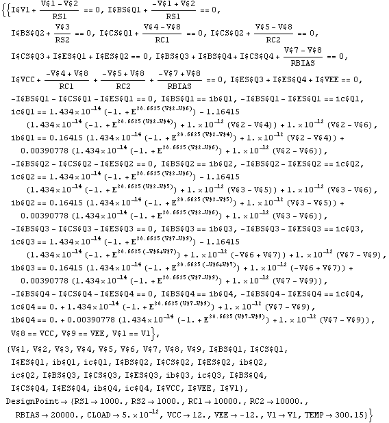
Then, we run NDAESolve sweeping the parameter V1 in the interval  . Note that the sweep variable can be any network parameter, for instance a voltage or current source parameter, a model parameter, or even any unknown in the system of equations. . Note that the sweep variable can be any network parameter, for instance a voltage or current source parameter, a model parameter, or even any unknown in the system of equations.
In[17]:= dctransfer = NDAESolve[staticequations, {V1, -0.5, 0.5}];
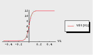
To display the DC-transfer curve graphically we again apply the function TransientPlot. For our DC-transfer analysis we want to plot the output voltage V$5 versus the input voltage V1:
In[18]:= TransientPlot[dctransfer, {V$5[V1]}, {V1, -0.5, 0.5}]
Out[20]= 
The resulting plot shows the typical  -shaped transfer characteristic of this type of differential amplifier. -shaped transfer characteristic of this type of differential amplifier.
Parametric Analyses
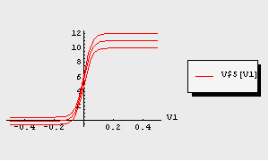
Finally, we demonstrate the usage of NDAESolve for carrying out parametric analyses. As an example, we perform a parametric analysis of the above computed DC-transfer characteristic V$5[V1]. As additional sweep parameter we choose the positive reference voltage VCC which shall take the values  . Note that for parametric analyses NDAESolve returns a multi-dimensional data object (see Section 3.7.1). . Note that for parametric analyses NDAESolve returns a multi-dimensional data object (see Section 3.7.1).
In[19]:= paramdctransfer = NDAESolve[staticequations,
{V1, -0.5, 0.5}, {VCC, {10, 11, 12}}]
Out[21]= 
The above generated multi-dimensional data format is supported by TransientPlot. Thus, we can display all sweep traces of the DC-transfer characteristic in a single plot.
In[20]:= TransientPlot[paramdctransfer, {V$5[V1]},
{V1, -0.5, 0.5}]
Out[22]= 
|