|
Slider-Crank Example Mechanism for MechanicalSystems Kinematic Constraintsby Robert Beretta
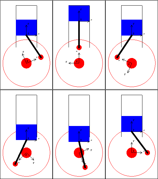
Slider-Crank AnimationDiscussionSlider-Crank Function This sample notebook analyzes the motion of a classic slider-crankshaft mechanism using MechanicalSystems. This mechanism is first modeled with a simple and intuitive set of mechanical constraints that are representative of how such a problem would usually be modeled. The same mechanism is then repeatedly modeled with different sets of constraints, all to achieve essentially the same end. In all, this single mechanism is used to demonstrate each one of MechanicalSystems basic constraint objects. Slider-Crank Model The kinematic model of the slider-crank mechanism consists of three bodies.
1. Ground (black)
2. Crank (red)
3. Slider (blue)
A real slider-crank mechanism would have a fourth body--the connecting link that attaches the crank to the slider. In the kinematic model, however, this body is modeled by a single constraint that specifies a constant distance between a point on the crank and a point on the slider. This technique decreases the overall size of the model. Kinematic ModelPreparation The Modeler2D package is loaded into Mathematica with the Needs command. The following symbols are used to reference each of the bodies in the model throughout the analysis. Body DefinitionsGround Three points must be defined on the ground (body 1).
P1. The location of the crank rotational axis on the ground.
P2 and P3. Two points to define the line upon which the slider slides. Crank Two points must be defined on the crank (body 2).
P1. The crank's rotational axis.
P2. The point where the connecting link attaches to the crank. Note that no initial guess has been given for the crank, thus the default initial guess  is used. is used. Slider Two points must be defined on the slider (body 3).
P1 and P2. Two points along the vertical axis of the slider. Build bodies The body objects are incorporated into the current model with the SetBodies command. ConstraintsThree constraints and one driving constraint are required to model the slider-crank mechanism. Note the naming convention of Modeler2D constraint objects--each constraint's head ends with a number that signifies the number of degrees of freedom constrained. Also note that the first argument to all constraint functions is an arbitrary constraint number. This integer must be unique among all constraints in a single model. Constraint 1 is a revolute joint, or pivot, between the crank and the ground.

Constraint 2 is a relative-distance constraint between the crank and the slider that replaces the pseudo connecting rod.

Constraint 3 is a translational or prismatic joint between the slider and the ground.

Constraint 4 is a rotational driver to turn the crank.

The driving function  causes body 2 to make one full revolution as T goes from 0 to 1. causes body 2 to make one full revolution as T goes from 0 to 1.
The constraint definitions are incorporated into the current model with the SetConstraints command. Running the ModelCheckSystem tests for certain modeling errors. A return value of True means all is well. SolveMech[t] runs the current model at time  and returns a list of rules containing the and returns a list of rules containing the  , ,  , and , and  coordinates of each body. coordinates of each body. The most current solution found by Modeler2D is always saved so that it can be used as the next initial guess. Whenever SolveMech is called, the most current solution rules are automatically updated. LastSolve[] returns the most current solution. GraphicsThe following graphic uses only one Modeler2D graphics function, Bar. The remainder of the image is generated entirely with built-in Mathematica graphics functions and the help of some Modeler2D functions providing the location coordinates of bodies in the model. This technique allows a graphic image to be created that is a function of the location of the bodies in the model, so that the graphic may be redrawn with the mechanism in different positions just by changing a set of replacement rules applied to the graphics object.
All of the Modeler2D graphics functions, such as Bar, return standard Mathematica graphics primitives whose coordinates are functions of location variables. The graphics object can now be displayed with Show. The graphics primitives are located in 2D space by applying a solution rule such as the current default initial guess LastSolve[], or the return of SolveMech.
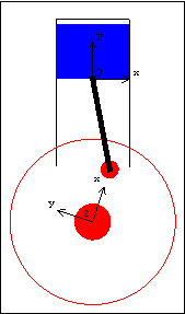
The following input will generate the series of 16 graphics in the animation cell at the beginning of this notebook. ConstraintsOriginLock2 Another constraint that could replace the Revolute2 constraint, in this case, is OriginLock2. OriginLock2 does not reference any particular points on the bodies it constrains, rather it directly constrains the variables that define the location of a body, which is the same as referencing the origin of a body. In this case, OriginLock2 can replace the Revolute2 constraint used in the slider-crank model, because the Revolute2 constraint referenced the origins of both of the bodies. An optional last argument to OriginLock2 can be given that specifies the vector offset between the origins. Here we rebuild the constraints. The location of the center of the crank can now be changed through changing the values of xoffset and yoffset.
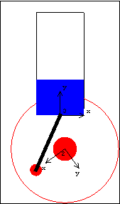
RotationLock1 RotationLock1 simply controls the angular coordinate of a body. Revolute2 The revolute joint is probably the single most common constraint in all kinematic models. DirectedPosition2 A revolute type constraint that allows an offset vector between the two points is DirectedPosition2. Thus, DirectedPosition2[a__, {0, 0}] is identical to Revolute2[a__]. Note that DirectedPosition2 allows the second point object to be omitted, defaulting to the global origin. This constraint set offsets the crank axis from its original base position.
The same result could be accomplished simply by setting the global coordinates of point 1 on the ground body to be {xoffset, yoffset}. However, this would not be true if the DirectedPosition2 constraint was applied between two bodies that were both rotating.
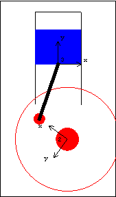
Translate2 Some of the Modeler2D constraint functions reference geometric lines or axes instead of points (Translate2, PointOnLine1, ...). Lines are specified by two points lying on a single body or two separate bodies and axes are specified by a point and a direction. This constraint is identical to constraint 3 used initially. PointOnLines2 PointOnLines2 is used to place a point at the intersection of two lines. Thus, the following constraint could be used to replace the Revolute2 constraint by forcing the center of the crank to lie at the intersection of two lines that intersect at the global origin. PointOnLine1 Instead of locating the slider with a single two degree of freedom constraint, a pair of one degree of freedom constraints can be used; one to enforce that one point on the slider moves along the specified axis, and one to enforce the slider's angular orientation. PointOnLine1 and RotationLock1 are used to do this. In this example, sliderangle sets the angular position of the slider through the RotationLock1 constraint (a very tippy slider!).
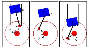
DirectedDistance1 The DirectedDistance1 constraint is effectively very similar to PointOnLine1 except in the method used to define the translation line. RelativeX1 and RelativeY1 The mechanism can be modeled with six one degree of freedom constraints by taking the previous model and replacing OriginLock2 with RelativeX1 and RelativeY1, each a one degree of freedom constraint. The pnt2 argument can be omitted, in which case it defaults to the global origin. This constraint set is identical to the previous one. RelativeAngle1 The relative angle between two bodies can also be controlled with RelativeAngle1. RelativeAngle1 uses vectors for reference, instead of using the angular coordinate of the body, like RotationLock1. The following constraint set is effectively the same as the previous one defined for PointOnLine1.
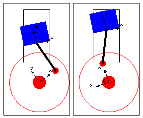
Parallel1 and Orthogonal1Two constraints that are actually special cases of RelativeAngle1 are Parallel1 and Orthogonal1. The following constraint set is effectively the same as the first one in this notebook.
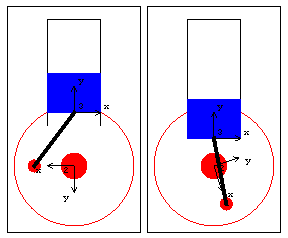
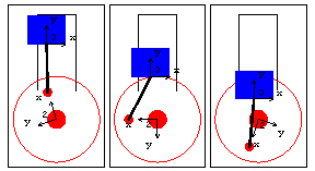
RelativeDistance1 RelativeDistance1 constrains a point to lie on a circular path. Optional ArgumentsPointOnLine1 has two optional arguments to offset or rotate the translation line, relative to the reference line. The following constraint set allows the slider to travel along a path that is offset and canted relative to the slider's original track. SetGuess[] must be run to reset the initial guesses or the model will converge upside down because of the large difference between the last solution time and the current one.
End
|