|
Mass-Bar Spatial Inertia Example for MechanicalSystemsby Robert Beretta

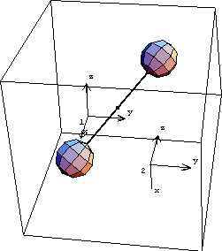
Mass-Bar AnimationDiscussionThis sample notebook analyzes the motion of a spatial mass-bar mechanism. The mechanism consists of two bodies.
1. Ground body (black)
2. Mass-bar (red)
The purpose of this model is to verify mass matrix generation in Modeler3D. The mass-bar is a solid object with inertia properties that are defined such that it has a primary axis of inertia that is not aligned with any of the local coordinate axes, and further that the primary inertia matrix has only two nonzero terms; the mass-bar is effectively a massless rod with two point masses on either end. The mass-bar also has a center of gravity that is not located on the local origin. The mass-bar is then constrained to rotate about its primary axis of inertia. Thus, all of the elements in the mass-bar's inertia matrix are nonzero, and the acceleration of the local origin is also nonzero, but the resultant forces due to its rotation must add to zero, because it is rotating about its primary axis. Kinematic ModelPreparationThe Modeler3D package is loaded into Mathematica with the Needs command. SetSymbols is used to change the way that Modeler3D represents derivatives in a solution. This causes the angular velocity and acceleration of each body to be formulated in terms of the time derivatives of Euler parameters. This causes the angular velocity and acceleration of each body to be formulated in terms of the three components of the global angular velocity vector and its derivative. This causes the angular velocity and acceleration of each body to be formulated in terms of the three components of the local angular velocity vector and its derivative. The following names are used to reference the bodies in the mass-bar. Body DefinitionsTwo points are defined on the ground (body 1).
P1. Origin of ground body.
P2. First point on the mass-bar axis. Three points are defined on the mass-bar (body 2).
P1. A point on the mass-bar axis.
P2. A second point to define the mass-bar rotational axis, along with P1.
P3. A second point, along with P1, to define a reference line for the graphic image. Constraint DefinitionsTwo constraints are required to model the mass-bar mechanism. 1. Spherical3. A constraint between one end of the mass-bar and a point on the ground.. 2. RotationLock3. A constraint to specify the orientation of the mass-bar, relative to the ground. The  term is used to give the mass-bar nonzero angular acceleration. term is used to give the mass-bar nonzero angular acceleration. Running the ModelGraphics

The following cells can be uncommented to generate the animation sequence at the beginning of this notebook. StaticsApplying no loads to the model is a fairly trivial case for the static solution. DynamicsThe reaction forces at all of the constraints are zero. Note that any change to the inertia properties causes the reactions to be nonzero. EnergyThe body has no kinetic energy because it has no inertia about its current rotational axis. Angular Momentum

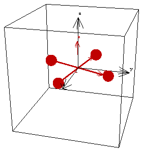
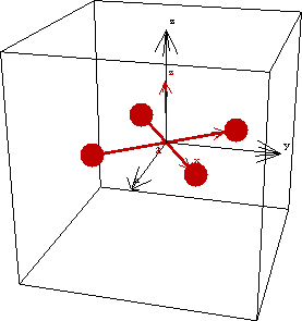
SetupThe following example demonstrates the inertia properties of a rotating body in 3D space. A body is defined (the flywheel) that is essentially four point masses located symmetrically about an axis of rotation. The body is spinning rapidly about its primary axis of inertia, but this axis of rotation is itself being rotated slowly about an orthogonal axis. Thus the angular momentum vector of the body is changing direction and the moment required to enforce this secondary rotation is directed orthogonally to both the spin axis and the axis of the secondary rotation. Kinematic ModelBody DefinitionsFour points are defined on the flywheel (body 2) to locate four point masses. Constraint DefinitionsTwo constraints are required to model the flywheel mechanism. 1. Spherical3. A constraint to locate the center of the flywheel. 2. RotationLock3. A single constraint to enforce both the primary and secondary rotations of the flywheel. The following two constraint sets are effectively the same. Running the ModelGraphics

The following cells can be uncommented to generate an animation sequence. ForcesNote that the angular acceleration is orthogonal to the angular velocity. The moment required to enforce the rotation of the body is entirely in the X direction. As the position of the flywheel is advanced the components of the angular velocity change, as do the components of the angular acceleration and the applied moment. End
|