|
Rocker Arms Example Mechanism for MechanicalSystemsby Robert Beretta
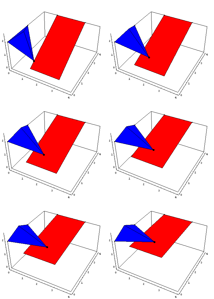
Rocker Arms AnimationDiscussionRocker FunctionThis sample notebook analyzes the motion of a pair of interconnected rocker arms in 3D space using MechanicalSystems. Both of the rockers pivot about axes affixed to the ground. The tip of the first rocker is in point contact with the planar surface of the second rocker, called the plate. A driver forces the drive plate to move up and down, which in turn moves the rocker. Rocker ModelThe mechanism consists of three bodies.
1. Ground (black)
2. Plate (red)
3. Rocker (blue) Kinematic ModelPreparationThe Modeler3D package is loaded into Mathematica. The following symbols are used to reference each of the bodies in the rocker model. Body DefinitionsThe kinematic constraints that make up the model enforce relationships between various points on the bodies of the mechanism. Each body must have a local coordinate system attached to it; the points then defined on each body are relative to that local system.
These points are defined for each body with a Body object. Body accepts a list of point locations and other properties of a body and returns a SysBody object that is passed to SetBodies to incorporate the data into the current model. GroundFive points are defined on the ground (body 1).
P1. The global origin.
P2. A second point (along with point 1) to define the direction of the plate axis.
P3. A point that lies on the plate axis.
P4. A second point (along with point 1) to define the direction of the rocker axis.
P5. A point that lies on the rocket axis. PlateFour points are defined on the plate (body 2).
P1 and P2. Two points along the plate's rotational axis.
P3 and P4. Two more points to define the other two corners of the rectangular plate. RockerFour points are defined on the rocker (body 3).
P1 and P 2. Two points along the rocker's rotational axis.
P3. The point where the rocker contacts the plate.
P4. A point used for the graphic image (to draw the backbone of the rocker). Build bodies The data contained in each of the body objects is incorporated into the current model with the Modeler3D SetBodies command. Constraint DefinitionsNow the kinematic constraints that make up the mechanism are defined. A library of simple constraints is defined by Modeler3D. Each constraint function returns a SysCon object that is used to build the system of equations representing the model.
Four constraints, including one driving constraint, are required to model the rocker mechanism.
1. A revolute joint, or pivot, between the plate and the ground.
2. A revolute joint between the rocker and the ground.
3. A translational joint that constrains the tip of the rocker arm to be placed on the surface of the plate.
4. A relative-distance driving constraint between the ground and the plate that forces the end of the plate to be a specified distance from the ground. Revolute5Four pieces of geometric data are required to define a 3D revolute joint--one line and one point on each of the two bodies involved. First, the two local points are constrained to be coincident with each other. Thus the two points define the axial and radial location of the pivot axis on each body. Second, the two local lines are constrained to be mutually parallel. Thus, the two lines define the direction of the pivot axis. Note that although the two lines may be coincident at the axis of the pivot, they do not need to be. They are intended only to be parallel, thus only their direction vectors are used in the constraint, not their positions.
The revolute joint constrains five degrees of freedom--three translational degrees of freedom from the two coincident points, and two rotational degrees of freedom from holding the two lines parallel.

In Modeler3D constraint syntax, points are specified as Point[body_number, point_number] referencing the previously defined entries in the points table.
Lines are specified with either three or four integers that define two endpoints of the line. 1. The following constraint is for the plate rotational axis. 2. A similar constraint is used for the rocker axis. PointOnPlane1A one degree of freedom constraint is used to enforce that the tip of the rocker moves within the plane of the plate. Only two pieces of data are required for this constraint--a point on one body and a plane on the other. PointOnPlane1 allows a third parameter--an offset distance between the point and plane. This parameter is zero by default.

Planes are specified with either four or six integers that define three noncolinear points in the plane. 3. The following constraint places the tip of the rocker on the plate. Any three of the four points on body 2 could have been chosen to define the previous plane, with identical results, because all four points are coplanar. RelativeZ1Finally, a one degree of freedom constraint is used to force the vertical position (relative to the global origin) of the tip of the plate (point 3 on body 2) to be equal to time T.

4. Here is the driving constraint. SetConstraintsSetConstraints incorporates the constraint objects into Mech's internal database. Running the ModelThe kinematic model is now complete. A convenient command to run before trying to run the model is CheckSystem. This tests that all the variables are defined. If CheckSystem returns True, you're O.K. SolveMech[t] runs the current model at time t and, if the model converges, returns a list of rules containing the X-Y-Z coordinates and Euler parameters of each body. For those unfamiliar with Euler parameters, suffice it to say that the four Euler parameters provide a robust means of defining the three degrees of freedom of the rotational orientation of a body in 3D space. Graphic OutputThe next step is usually to produce some graphic output to see if the model is what it is supposed to be. Modeler3D includes a library of graphics functions that return graphics primitives that are functions of dependent variables in the model. These graphic objects are located in 3D space by applying a solution rule that is returned by SolveMech. All of these functions return graphics objects that are functions of dependent variables. The graphics objects are located by applying a current solution rule.
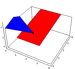
To obtain a sequence of solution points, an alternate syntax for SolveMech is used. This creates a table of nine position solutions spaced evenly from T = 0 to T = 2. The following input generates the series of 16 graphics in the animation cell at the beginning of this notebook (don't run it unless you are prepared to wait a while). LocusPlot plots the locus of a moving point.
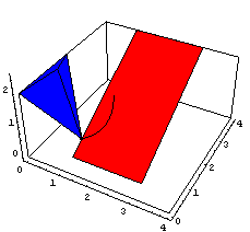
Output FunctionsLocation OutputNow that there is a solution configuration for the model, whatever output is desired can be extracted. If information such as the value of one of the local origin coordinates is desired, it can be taken directly from the most recent solution rule, LastSolve[]. More useful output is obtained from from a library of output functions contained in Modeler3D, such as. FindTimeGraphing Output FunctionsThe list of location solutions previously obtained by postab can be used to generate plots of any obtainable measurement in the mechanism.
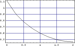
The following plot shows the X position of the tip of the rocker as function of the height of the plate.
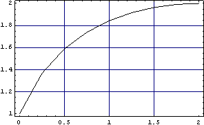
The following plot shows the angle of the rocker as a function of the height of the plate.
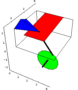
VelocityVelocity SolutionWith the option , SolveMech generates the complete location solution, and the first time-derivative of the location coordinates of all of the bodies. SolveMech then returns the solution rule, , containing both the position and velocity terms at time T.Velocity OutputFindTimeAccelerationAcceleration SolutionHere the existing solution rule LastSolve[] is updated with an acceleration solution. FindTimeAdding a BodyA fourth body is added to the existing model simply by creating a new Body object, and the required constraint objects, and rerunning SetBodies and SetConstraints. A crank and connecting rod are added to the model to replace the simple RelativeZ1 driver. A sixth point is added to the ground body to locate the center of the crank. 4. A relative distance constraint replaces the RelativeZ1 driver to model the connecting rod. 5. A revolute joint is added to constrain the axis of the crank. 6. A driving constraint is added to rotate the crank. This builds and checks the new constraint set. Here is the graphic of the crank only. Here is the image of the entire model.
End
|