11.3.1 Two-Link Manipulator ExampleIt is often useful to find the mass matrix of a model with respect to an alternative coordinate system. When generalized coordinates are used, Mech automatically generates the model's mass matrix in terms of the specified coordinates, and converting the mass matrix to another consistent coordinate system is a straightforward process.
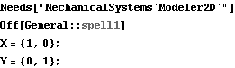
An open-loop two-link manipulator model is developed to demonstrate the conversion of a mass matrix from one coordinate system to another. The model has two moving bodies, link 1 and link 2, which are represented by two generalized coordinates, alpha and beta. The alpha coordinate represents the rotation angle of link 1 relative to the ground and beta represents the rotation of link 2 relative to link 1. This loads the Modeler2D packages and defines some useful constants. Here is a graphic of the two-link manipulator model.
Bodies Two body objects are used in the manipulator model. Each body object is used only to define inertia properties for the body, no local point definitions are made. Thus the ground (body 1) needs no body object because its inertia is immaterial. Note that the lengths of the links are left as parameters L1 and L2, causing the resulting mass matrix to be completely general. Here are the body objects for the manipulator model. The inertia properties are incorporated into the model. ConstraintsFour constraint objects are used to model the manipulator. Two constraints are generalized coordinate constraints that introduce the two degrees of freedom, alpha and beta, and the other two constraints simply constrain these two degrees of freedom. A GenRevolute2 constraint sets up the relationship between link 1 and the ground.A GenRevolute2 constraint sets up the relationship between link 2 and link 1.Two Constraint objects constrain alpha and beta to be equal to the parameters q1 and q2.Note that L1 appears explicitly in constraint 3 to locate the tip of link 1 where it is attached to link 2. Here are the constraint objects for the manipulator. The constraints are incorporated into the current model. Mass MatrixThe kinematics of this model are truly trivial. The entire constraint set is nothing more than a pair of expressions setting alpha and beta equal to q1 and q2. There is really no point in running the model at all, in the normal sense in which other Mech models are run because the configuration of the model can be specified directly by alpha and beta. The usefulness of the model lies in the other definitions that have been made by Mech for inertia properties and coordinate transformations. Here is the constraint vector.
Out[16]= |  |
Here is the global location of the tip of link 2.
Out[17]= |  |
Here is the  system mass matrix. system mass matrix.
Out[18]= | 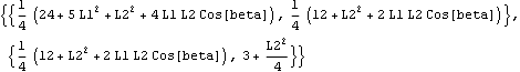 |
Endpoint MobilityNow we wish to find the ellipse of mobility of the endpoint of link 2. The ellipse of mobility of an equivalent two-link manipulator model was found in Section 10.3. In that example, a one-unit force was applied to the endpoint of link 2 while varying the direction of the force through 360 degrees, and the resulting free acceleration vector of the endpoint was found with the SetFree and SolveFree functions.
This section presents a more elegant method of finding the ellipse of mobility directly from the mass matrix. The method presented in Section 10.3 is much more general than this one in that this method (as it is presented here) is restricted to finding the mobility of the endpoint at zero velocity, and is restricted to models that have the same total number of coordinates as the number of physical degrees of freedom of the endpoint.
The basic trick here is to convert the mass matrix from the generalized (joint angle) coordinates to endpoint coordinates. The mass matrix m, in the context of  , transforms accelerations of the generalized coordinates a, which are the relative angular accelerations of each of the joints, into forces on the generalized coordinates f, which are moments applied at the joints. We need to have a matrix P in , transforms accelerations of the generalized coordinates a, which are the relative angular accelerations of each of the joints, into forces on the generalized coordinates f, which are moments applied at the joints. We need to have a matrix P in  , which transforms a force vector F applied to the endpoint into the linear acceleration vector A of the endpoint. First, we need a transformation matrix J from generalized coordinates to endpoint coordinates such that , which transforms a force vector F applied to the endpoint into the linear acceleration vector A of the endpoint. First, we need a transformation matrix J from generalized coordinates to endpoint coordinates such that  . Then . Then  . .
The matrix J is the Jacobian of the global coordinates of the endpoint. Here is the transformation matrix J.
Out[19]= |  |
Here is the inverse endpoint mass matrix P, a rather large symbolic matrix. We can now find the acceleration of the endpoint that results from any force vector at any particular configuration simply by multiplying P times the force vector. Here is the acceleration vector resulting from an applied force {0, 2}.
Out[22]= | 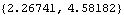 |
Now finding the ellipse of mobility is simply a matter of applying a unit force vector that revolves through a full circle and plotting the components of the resulting acceleration. Here is the ellipse of mobility.
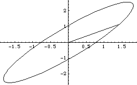
Out[23]= |  |
|