8.2 Kinematic and Dynamic SolutionsThis section describes the function of Mech's inverse dynamics solution block. Inverse dynamics allows the dynamic reaction forces in a fully kinematically constrained model to be found. The motion of such a model is completely defined by the kinematics of the model, only the reaction forces that result from the constrained motion are found through inverse dynamics. To find the free response of a model with one or more degrees of dynamic freedom, consult Chapter 10. 8.2.1 Dynamics OptionsOnce the kinematic constraints and the inertia properties of a body have been defined, the dynamic forces in a mechanism can be determined. The Solution option to SolveMech is used to tell Mech to calculate the generalized reaction forces in the model and to include the forces due to inertia. An option for SolveMech. The purpose of the Kinematic setting is to allow for velocity-dependent loading, such as damping, while still not including the dynamic loading. Note that using the Static setting does not necessarily produce an error in a model that has velocity-dependent loading, because Static sets the velocities to zero. This condition may result in an incidental error, however, if the velocity-dependent terms happen to blow up at zero velocity.
The Dynamic setting calculates the mechanism accelerations and then adds the inertial loads due to the acceleration of each body to the model's applied load vector before calculating the generalized reaction forces. Note that the Dynamic setting must be used to include the centrifugal forces, even though they depend on velocity and not acceleration. 8.2.2 3D Example MechanismA Modeler3D example model is developed to demonstrate a simple gyroscopic inertial loading condition. The model is a flywheel with an angular velocity vector with a changing direction.
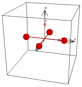
The model consists of only one moving body, the flywheel. The flywheel spins about an axis that is attached to the ground at one point. The axis of rotation of the flywheel is then rotated about another nonparallel axis affixed to the ground. Thus, the direction of the axis of rotation of the flywheel changes with time. This loads the Modeler3D package. Here is a graphic of the flywheel model.

The Method -> Angular option is given to SetSymbols before building any other part of the flywheel model. This is done so that the angular velocity and angular acceleration of the flywheel is calculated directly, instead of being calculated in terms of derivatives of Euler parameters. Note that this is not a necessary step to obtain the dynamic forces. This causes angular velocities to be calculated directly so that it won't be necessary to convert the Euler parameters into angular velocity. InertiaThe flywheel is modeled by four one-unit point masses, symmetrically placed about the axis of rotation. The Modeler3D CompositeInertia function can be used, trivially, to find the net inertia properties of the flywheel.
Out[4]= |  |
BodiesOne body object is defined for the flywheel model. The ground body does not have a body object because it has no inertia or required point definitions. The body object for the flywheel contains the inertia properties and the locations of each of the four point masses. Names are defined for each of the body numbers in the model. Here is the body object for the flywheel. ConstraintsThree constraints, two of which are functionally dependent on time, are required to model the flywheel mechanism.
A Spherical3 constraint places the center of the flywheel at the global origin.
A Parallel2 constraint forces the axis of rotation of the flywheel to be parallel with a specified vector on the ground body. The direction of the axis vector on the ground body is explicitly a function of time T. This constraint effectively causes the axis of rotation of the flywheel to change direction with time.
A ProjectedAngle1 constraint rotates the flywheel about its axis. Note the choice of the vector that was used on the ground body. The vector in the Y direction on the ground body is always normal to the axis of rotation of the flywheel. If a vector in the X direction was chosen instead, the constraint would become singular at T = 0.25. Note also that the flywheel is spinning 10 times more rapidly about its symmetry axis than its axis is rotating with respect to the ground. Here are the constraint objects for the flywheel. RuntimeBecause of the presence of T in the constraints, the model can be run through its intended range of motion by varying T directly with the SolveMech command. Now run the model at T = 0.02.
Out[10]= |  |
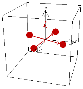
Here is the flywheel at T = 0.02.

8.2.3 Inertial LoadingNo forces are applied to the model with SetLoads because only the inertial loading of the flywheel is being considered. All of the inertia properties have already been defined, so all that must be done to find the dynamic solution is to request it of SolveMech with the solution option. The dynamic solution at T = 0.
Out[11]= |  |
The angular velocity and acceleration of the flywheel can be read directly from the solution rules returned by SolveMech, or Modeler3D output functions can be used. Note that the angular acceleration is orthogonal to the angular velocity. Here are the angular velocity and acceleration of the flywheel.
Out[12]= |  |
The moment that is applied to the flywheel to enforce the specified rotation is the reaction force to constraint 2, the constraint that controls the direction of the axis of the flywheel.
Note that the reaction to constraint 3 is zero. No moment is required to spin the flywheel about its primary axis, only to change the direction of the axis. Here are the moments that are applied to the flywheel by the constraints.
Out[13]= |  |
Out[14]= |  |
As the position of the flywheel is advanced in time, the components of the angular velocity change, and the components of the angular acceleration and the applied moment follow. This calculates the dynamic solution at T = 0.01. Here are the angular velocity and acceleration.
Out[16]= |  |
Here is the applied moment.
Out[17]= |  |
Undocumented Graphics Generation
|