WOLFRAM SYSTEMMODELER
GettingStartedA step-by-step guide to running your first model with OPCUA |
|
Information
This getting started guide will provide you with the basic knowledge needed to use OPCUA. If you are new to OPC, it is recommended that you visit the OPC Foundation webpage to get more acquainted with this protocol and common terms related to it.
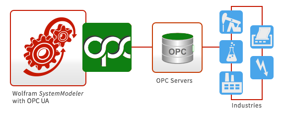
OPC UA for Industrial Communication
While the OPCClassic Library is limited to communication between Windows computers, being based on the proprietary Component Object Model (COM) interface, OPC UA can be used to communicate on many other platforms, such as Windows, OS X, Linux, and Raspberry Pi. Communication between different platforms is also possible using the OPCUA Library.
The OPC UA specification supports reading data in real time from nodes and reading historical data. OPC UA also has support for scalability, multithreading, and security. To see what is implemented in the OPCUA Modelica library here in SystemModeler, see Limitations at the bottom of this page.
Prerequisites
To be able to perform the steps in this tutorial, you need the following:
Installations:
- The OPCUA Library
- An open62541 Simulation Server
Other:
- If you would like to customize the open62541 Simulation Server, see instructions on the library here and how to build the server yourself here.
You also need a basic knowledge of SystemModeler. It is recommended that you check out the learning resources at the Wolfram webpage if you need to brush up on your SystemModeler skills.
Connecting to an OPC UA Server
To be able to use OPCUA, you need to establish a connection to an OPC UA server running on a local or remote host. For more information on this, see the section on Common OPC UA Issues at the end of this tutorial.
Building a Model with Multiple Servers
As a first exercise, you will reproduce the example model OPCUA.Examples.MultipleServers that is shipped with OPCUA. It demonstrates conceptually how to connect to two different OPC servers.
Starting Example Servers
The first thing you need to do, is to make sure you have access to starting an OPC Server. In this particular example, you actually have to have access to two servers. Included in the OPCUA Library are two example servers, built using the open62541 library. They can be found by following this link. If you are on a Windows machine, start the file StartExampleServers.bat, or if you are on another operating system, such as Linux or OS X, start the file StartExampleServers.
Building the Model
After you have successfully started the simulation servers, you can start to build your model. To do so, you need to locate the following components:
- Modelica.Blocks.Continuous.Filter (from the Modelica Standard Library)
- Modelica.Blocks.Sources.CombiTimeTable (from the Modelica Standard Library)
Create a new model in SystemModeler and drag each component onto the diagram view. Connect the components as shown in Fig. 1.

Fig. 1. Diagram view of OPCUA.Examples.MultipleServers.
Parameterizing the Model
Next, you need to specify certain component parameters.
Start with the component named opcServer, shown in Fig. 2. Select the component and click the General tab at the bottom of the main window.

Fig. 2. The opcServer component.
In the Parameters view, you will find the parameter hostName. hostName needs to be specified for each instance of the server object.
Since the the simulation servers have been started on your user account on your local computer, "localhost" can be kept as hostName.

Fig. 3. The General view of the opcServer component, with all parameters specified.
Repeat the procedure for the second OPC server component ( opcServer1 in Fig. 1), but in this case use the hostName "opc.tcp://localhost:16665".
Move on to component readReal. Again, select the component and click the General tab.

Fig. 4. The readReal component highlighted.
The interesting parameters here are nodeID, nodeIDType, and nodeNamespace. Together they identify the node on the server that you want to read data from (or write data to, if this has been a block for writing data). The node you specify has to exist on the server, and it has to be available for the kind of operation you want to perform, as some items are available for either reading or writing but not both.
Enter these values under the General tab on the readReal component:
readReal
- samplePeriod: 0.1 s
- startTime: 0 s
- nodeID: "51031"
- nodeIDType: OPCUA.Types.UANodeIdType.NumericId
- nodeNamespace: 1

Fig. 5. The General view of the readReal component, with all parameters specified.
For the remaining components, choose the following parameters:
writeReal
- samplePeriod: 0.1 s
- startTime: 0.1 s
- nodeID: "51031"
- nodeIDType: OPCUA.Types.UANodeIdType.NumericId
- nodeNamespace: 1
writeRealTable
- samplePeriod: 0.1 s
- startTime: 0 s
- nodeID: "51031"
- nodeIDType: OPCUA.Types.UANodeIdType.NumericId
- nodeNamespace: 1
filter
- analogFilter: Modelica.Blocks.Types.AnalogFilter.Butterworth
- filterType: Modelica.Blocks.Types.FilterType.LowPass
- order: 3
- f_cut: 0.2 Hz
- f_min: 1.6 Hz
combiTimeTable
- table[:,:]: {{0, 10}, {1, 9}, {5, 3}, {8, 2}, {11, 6}, {14, 3}, {15, 8}, {16, 5}, {18, 10}, {22, 7}, {24, 5}, {25, 1}, {27, 6}, {30, 10}}
The combiTimeTable is providing values that have been randomly generated and that will be written to the opcServer at specific times. These will then be read filtered and then written to the other server, opcServer1. The function of the filter is to slow the rate of change coming from the random values from the combiTimeTable .
Understanding the Model
What does this model do exactly?
First of all, it connects to two OPC servers. The OPC servers are both running locally but on different ports (16664 and 16665).
If you would like to connect to remote servers, you would have to have access to another server (or two servers) on a remote host. To connect to that server, hostName (name of host or IP address with port number) would need to be updated to fit the address of the remote host.
The first server, opcServer, is connected to a write block, writeRealTable, that is writing values to node 51031 on the server from a combiTimeTable. The server is also connected to a read block, readReal, that reads data from node 51031 on the server every 0.2 seconds (as specified by parameter samplePeriod). The sampled signal is then run through a Butterworth lowpass filter with a cutoff frequency of 2.0 Hz. The filtered signal is sampled by writeReal and finally written to opcServer1, a second instance of the OPC server.
The model exemplifies a possible use of multiple OPC UA servers in one model, where one server is used for reading data and the other for writing data.
Simulating the Model
You are now getting ready to simulate your newly built model, which brings up the issue of which experiment settings to use for the simulation. For the majority of all practical applications of OPCUA, "Fixed step explicit Euler", with a step size of your choice, should be used as the solver method. For this scenario, use a step size of 0.01 s. Simulate for 30 s. You should also check the Synchronize with real time checkbox.

Fig. 6. The experiment settings specified for the MultipleServers model.
The first time you simulate the model, if the Synchronize with real time checkbox is unchecked, the simulation is probably too fast for you to actually see what is happening in the simulation. The reason is that SystemModeler simulates the model as fast as possible by default in this case. In order to study the simulation in real time, you can also check the Synchronize with real time checkbox in Simulation Center (see Fig. 7).

Fig. 7. Check the Synchronize with real time option in the Settings tab in Simulation Center.
If you are building many models with OPCUA, consider setting the Synchronize with real time option as a default simulation setting. This is done by going to Tools ► Options and choosing Default Experiment under the Simulation Center header. There, check the Synchronize with real time checkbox.
To see the data sampled from the first server, opcServer, plot readReal.y over time. The signal should be similar to that in Fig. 8 below. It will probably not be identical to Fig. 8, since different simulations read data from the server item at different times.
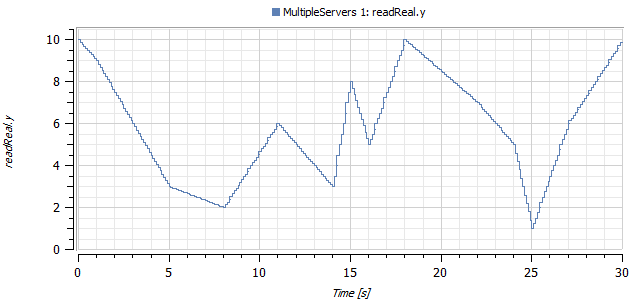
Fig. 8. The sampled data read from opcServer.
Plot the filtered signal and the sampled signal in the same plot.
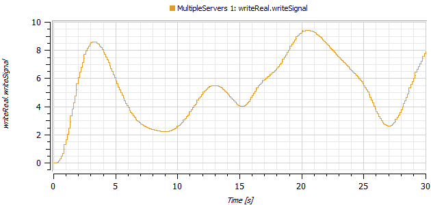
Fig. 9. The sampled signal writeReal.writeSignal .
Troubleshooting
Connecting to a Remote Host
When connecting to an OPC server on a remote host, you will have to be able to connect to that host from the machine you are using. If you are not certain, try to ping the remote host to see if you can connect to it.
Common OPC UA Problems
If you are having other problems with your OPCUA models, going through the following checklist might help.
- Do your server components have specified hostNames?
- Do your block components have specified sampling periods, nodeIDs, nodeNamespaces, and nodeIDTypes?
- Do all nodeIDs and hostNames have quotation marks?
- Are the blocks trying to access nodes of the correct type? Blocks that read or write data of a certain type are only compatible with OPC UA nodes of that same type.
- Are the nodes you are trying to access available for the type of operation you want to do? Some nodes are available for reading or writing only, not both.
- Is the OPC UA server you are using really active and running on the host computer?
If you are still experiencing problems, visit http://community.wolfram.com and ask a question, or contact support@wolfram.com.
Limitations
This implementation of OPCUA handles reading and writing values to nodes of the types Real, Integer, and Boolean. The nodes should also be scalar; i.e. no arrays or matrix nodes can be read or written to. There is currently no support for reading historical values in OPCUA.
Wolfram Language
In[1]:=

SystemModel["OPCUA.GettingStarted"]
Out[1]:=