|
3.11.2 ApproximateTransferFunction

Command structure of ApproximateTransferFunction.
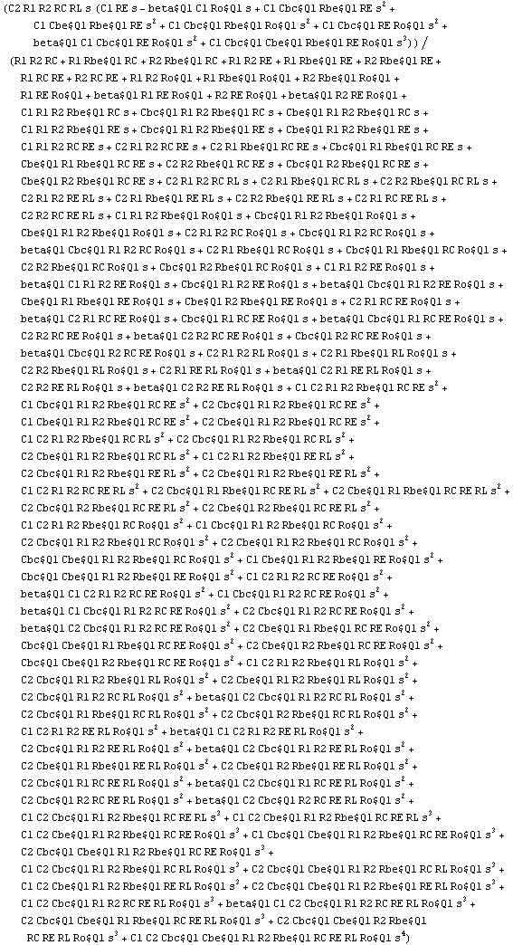
ApproximateTransferFunction approximates a symbolic transfer function by discarding insignificant terms from its coefficients (simplification after generation, SAG). The significance or insignificance of a term is evaluated on the basis of numerical reference values for the symbols (the design point). For each coefficient, the algorithm removes the numerically least significant terms until the maximum coefficient error is reached.
 See also: ApproximateMatrixEquation.
Examples
Below, we approximate the transfer function of the common-emitter amplifier. We allow for a maximum error of  in all coefficients of powers of the complex frequency in all coefficients of powers of the complex frequency  . .
Load Analog Insydes.
In[1]:= <<AnalogInsydes`
Define an AC model for BJTs.
In[2]:= Circuit[
Model[
Name -> BJT,
Selector -> AC,
Scope -> Global,
Ports -> {B, C, E},
Parameters -> {Rbe, Cbc, Cbe, beta, Ro,
RBE, CBC, CBE, BETA, RO},
Definition -> Netlist[
{CBE, {B, E}, Symbolic -> Cbe, Value -> CBE},
{RBE, {X, E}, Symbolic -> Rbe, Value -> RBE},
{CBC, {B, C}, Symbolic -> Cbc, Value -> CBC},
{CC, {B, X, C, E},
Symbolic -> beta, Value -> BETA},
{RO, {C, E}, Symbolic -> Ro, Value -> RO}
]
]
] // ExpandSubcircuits;
This netlist describes a common-emitter amplifier.
In[3]:= ceamplifier =
Circuit[
Netlist[
{V1, {1, 0}, 1},
{V0, {6, 0}, 0},
{C1, {1, 2}, Symbolic -> C1, Value -> 1.0*^-7},
{R1, {2, 6}, Symbolic -> R1, Value -> 1.0*^5},
{R2, {2, 0}, Symbolic -> R2, Value -> 47000.},
{RC, {6, 3}, Symbolic -> RC, Value -> 2200.},
{RE, {4, 0}, Symbolic -> RE, Value -> 1000.},
{C2, {3, 5}, Symbolic -> C2, Value -> 1.0*^-6},
{RL, {5, 0}, Symbolic -> RL, Value -> 47000.},
{Q1, {2 -> B, 3 -> C, 4 -> E},
Model -> BJT, Selector -> AC,
CBE -> 30.*^-12, CBC -> 5.*^-12, RBE -> 1000.,
RO -> 10000., BETA -> 200.}
]
]
Out[3]= 
Set up a system of symbolic AC equations.
In[4]:= eqs = CircuitEquations[ceamplifier,
ElementValues -> Symbolic]
Out[4]= 
Compute the complexity estimate.
In[5]:= ComplexityEstimate[eqs]
Out[5]= 
Compute the voltage transfer function symbolically and extract the result from the solution vector.
In[6]:= solution = Solve[eqs, V$5];
v5 = Together[V$5 /. First[solution]]
Out[7]= 
Get the design-point information from the DAEObject.
In[7]:= dp = GetDesignPoint[eqs]
Out[8]= 
Discard insignificant terms in the transfer function.
In[8]:= sag = ApproximateTransferFunction[v5, s, dp, 0.2]
Out[9]= 
Determine the complexity of the approximated expression.
In[9]:= Length[Denominator[sag]]
Out[10]= 
Simplify the result.
In[10]:= Simplify[sag]
Out[11]= 
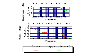
To validate the result, we compute the frequency response of the original system numerically and compare it graphically with the approximated result.
Compute the frequency response numerically.
In[11]:= acsweep = ACAnalysis[eqs, V$5, {f, 1, 1.0*^9}]
Out[12]= 
Evaluate the approximated expression numerically.
In[12]:= sagn[s_] = sag /. dp
Out[13]= 
Plot the exact and approximated functions together.
In[13]:= BodePlot[acsweep, {V$5[f], sagn[2 Pi I f]},
{f, 1, 1.0*^9}, TraceNames -> {"Exact", "Approximated"}]

Out[14]= 
|