|
2.4.2 Circuit Equations
The Command CircuitEquations
Setting up systems of symbolic circuit equations is done by the Analog Insydes command CircuitEquations, which takes a Netlist or Circuit object as first argument. In addition, the function may be called with a variety of options - to be introduced later - with which many aspects of equation setup can be influenced individually:
CircuitEquations[circuit, options]
If the type of the netlist argument is not a flat netlist, then the function ExpandSubcircuits is automatically applied to the circuit description in order to produce a flat netlist object before proceeding with equation setup.
This section describes how to set up equations of linear circuits in the Laplace domain. CircuitEquations can also be used to set up DC or transient equations for nonlinear circuits. This topic is discussed in Section 2.6.4.

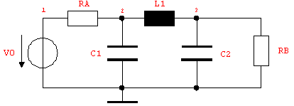
Figure 4.1: RLC filter circuit
To illustrate equation setup let's write down the netlist of the RLC filter circuit displayed in Figure 4.1.
In[1]:= <<AnalogInsydes`
In[2]:= rlcfilter =
Netlist[
{V0, {1, 0}, V0},
{RA, {1, 2}, RA},
{C1, {2, 0}, C1},
{L1, {2, 3}, L1},
{C2, {3, 0}, C2},
{RB, {3, 0}, RB}
]
Out[2]= 
By default, CircuitEquations sets up a system of modified nodal (MNA) equations in the frequency domain, or, more precisely, the Laplace domain. In the Laplace domain, all linear dynamic elements are described by frequency-dependent complex admittances or impedances, obtained by Laplace-transforming the corresponding constitutive equations. For instance, a linear capacitance  with a constitutive equation with a constitutive equation  is represented by its complex admittance is represented by its complex admittance  , where , where  denotes the complex Laplace frequency. denotes the complex Laplace frequency.
Unless specified otherwise (see netlist option Pattern in Section 3.1.4), all impedances, i.e. resistors and inductors, are automatically converted to their admittance equivalents. Therefore, the complex impedance  of an inductor of an inductor  will be treated as an admittance with the reciprocal value will be treated as an admittance with the reciprocal value  . .
In[3]:= rlceqs = CircuitEquations[rlcfilter]
Out[3]= 
The return value of CircuitEquations is a DAEObject which contains the three components of the linear matrix equation  , where A is the MNA matrix, x the vector of unknown node voltages and impedance branch currents, and b the vector of independent source voltages and source currents. To display the system of equations in a more readable form we can apply the command DisplayForm to the DAEObject rlceqs: , where A is the MNA matrix, x the vector of unknown node voltages and impedance branch currents, and b the vector of independent source voltages and source currents. To display the system of equations in a more readable form we can apply the command DisplayForm to the DAEObject rlceqs:
In[4]:= DisplayForm[rlceqs]
Out[4]//DisplayForm= 
Solving Circuit Equations
Systems of circuit equations generated by Analog Insydes can be solved symbolically by means of the command Solve. The sequence of arguments may have one of the following three forms, depending on which variable or set of variables the equations should be solved for:
Solve[dae]
Solve[dae, var]
Solve[dae,   , ,  , ,   ] ]
If Solve is called with a DAEObject only and no second argument is given then the solutions for all variables contained in the vector x are computed. If, in addition to the DAEObject, one single variable of x is specified as second argument then only this variable is solved for. To compute the solutions for a subset of x containing more than only one variable, the second argument must be a list of the variables of interest.
Solve finds all solutions of an equation system only for linear equations. For nonlinear (dynamic) equations it is in general not possible to find symbolic solutions. Thus, Analog Insydes provides the command NDAESolve to compute the solution of nonlinear DAE systems numerically. See Chapter 2.7 for details.
Just like Mathematica's built-in Solve function, Solve[dae] returns a list of rules {{var -> solution,  }} which associate the variables with the corresponding solutions. Individual solutions can be extracted from the list by using Mathematica's ReplaceAll operator (or /. in short notation). }} which associate the variables with the corresponding solutions. Individual solutions can be extracted from the list by using Mathematica's ReplaceAll operator (or /. in short notation).
Let's solve the MNA equations of the RLC filter for the node voltages at nodes 1 and 3. Since we are only interested in solving for two out of all four variables, we must use the third calling format:
In[5]:= rlcsol = Solve[rlceqs, {V$1, V$3}]
Out[5]= 
As indicated above, we can retrieve the solution for a particular variable using the /.-operator. The following input line serves to extract the value of V$3. The Mathematica command First removes the outer level of list brackets from the set of solutions, so the result is returned as a single expression and not as a list.
In[6]:= rlcv3 = V$3 /. First[rlcsol]
Out[6]= 
Quite frequently, the raw solutions computed from symbolic circuit equations are not presented in an immediately comprehensible form. It usually takes some additional mathematical postprocessing to transform the results into something which is easier to read or technically more meaningful. Mathematica provides several commands for rearranging expressions, such as Simplify, Factor, Together, Apart, or Collect. The choice of which function to use depends heavily on the particular application, and often some experimenting is required until the results are satisfactory.
For example, in the case of the above expression for V$3, we may want to combine all coefficients belonging to the same power of s into one single coefficient each. For this purpose, we apply a rewrite rule to all Plus subexpressions (i.e. sums) which groups the terms by corresponding powers of s and then pulls out the  . This yields a transfer function with coefficients in the canonical sum-of-products form. . This yields a transfer function with coefficients in the canonical sum-of-products form.
In[7]:= rlcv3 /. p_Plus :> Collect[p, s]
Out[7]= 
|