|
2.6.2 Defining Behavioral Models
The Argument Sequence of the Model Command for ABM Definitions
Behavioral models are defined using the Model command, just like subcircuits (see Section 2.3.2). Analog Insydes recognizes a request to define a behavioral model by the presence of the named parameter Variables and the absence of a subcircuit Netlist on the right-hand side of the Definition argument in a Model call. The full syntax for an ABM definition is shown below. Again, slanted typewriter font denotes optional arguments.
Model[
Name -> subcircuit class name,
Selector -> selector,
Scope -> scope,
Ports ->  port nodes port nodes , ,
Parameters ->  parameters parameters , ,
Symbolic ->  symbolic parameters symbolic parameters , ,
Defaults ->  defaults defaults , ,
InitialConditions ->  initial conditions initial conditions , ,
InitialGuess ->  initial guess initial guess , ,
Translation ->  parameter translation rules parameter translation rules , ,
Variables ->  variables variables , ,
Definition -> Equations[equations]
]
Except for the additional arguments and the keyword Definition, all other named arguments of the Model function have the same meaning as for subcircuit definitions. Following, we discuss the two arguments Definition and Variables.
Example: A Diode
Let's illustrate the steps which are necessary to define a behavioral model by implementing a nonlinear device model for a junction diode.

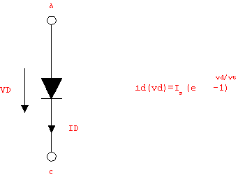
Figure 6.1: Junction diode
The diode shown in Figure 6.1 has two terminals, the anode and the cathode, denoted by the node identifiers A and C, respectively. The branch voltage  and the branch current and the branch current  satisfy the device equation satisfy the device equation

where  denotes the reverse-bias saturation current and denotes the reverse-bias saturation current and  the thermal voltage. Typical values for the thermal voltage. Typical values for  are are  . .  is given by is given by  where where  denotes Boltzmann's constant ( denotes Boltzmann's constant ( ). ).  is the absolute temperature (in Kelvin), and is the absolute temperature (in Kelvin), and  is the charge of an electron ( is the charge of an electron ( ). ).
In[1]:= <<AnalogInsydes`
In[2]:= ThermalVoltage[T_] := 1.381*10^-23 * T / (1.602*10^-19)
At a temperature of  ( ( ), ),  is approximately is approximately  : :
In[3]:= ThermalVoltage[300.]
Out[3]= 
Since the thermal voltage is only defined in terms of constants and the global quantity temperature,  is a global parameter. Thus, we have a local parameter of the diode device equation which is is a global parameter. Thus, we have a local parameter of the diode device equation which is  , and a global parameter which is , and a global parameter which is  . Note that a global parameter param is defined by setting Global[param] in the Parameters argument. Assuming Scope -> Local and no Translation rules, the first half of the Model definition is thus given by . Note that a global parameter param is defined by setting Global[param] in the Parameters argument. Assuming Scope -> Local and no Translation rules, the first half of the Model definition is thus given by
Model[
Name -> Diode,
Selector -> DC,
Ports -> {A, C},
Parameters -> {Is, Global[Vt]},

]
The Definition Argument
For behavioral model definitions, the Definition parameter must be of the form
Definition -> Equations[ , ,  , ,  ] ]
where  , ,  , ,  denote the symbolic device equations. (For compatibility reasons the right hand side of the Definition parameter may also be a list of equations.) When specifying an arbitrary set of equations we must tell Analog Insydes how the unknowns of the equations relate to the port currents and voltages of a model object. denote the symbolic device equations. (For compatibility reasons the right hand side of the Definition parameter may also be a list of equations.) When specifying an arbitrary set of equations we must tell Analog Insydes how the unknowns of the equations relate to the port currents and voltages of a model object.

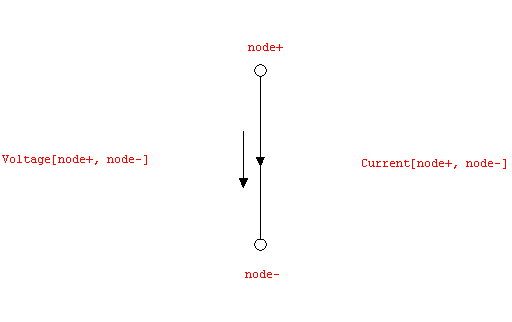
Figure 6.2: Voltage and current identifiers at a model port branch
Ports of behavioral models are defined in terms of electrical port branches. Every unique pair of node identifiers [node+, node-] introduces an electrical port branch in between the model port nodes node+ and node-. For the associated port voltage and current the positive reference direction is defined to be oriented from node+ to node-, which is illustrated in Figure 6.2.
Port variables in behavioral model equations can be referred to by means of two special keywords which are recognized by Analog Insydes and replaced by the corresponding global current or voltage identifiers during model instantiation and expansion. The keywords provided to make references to port currents and voltages are, respectively:
Current[node+, node-]
Voltage[node+, node-]
Note that the above definition of positive reference directions implies that Current[nodeA, nodeB] and Current[nodeB, nodeA] are two different quantities and refer to different port branches. Similarly, Current[nodeA, nodeB] and Voltage[nodeB, nodeA] do not refer to the same port branch.
In the case of the diode we have two port nodes A and C, which are connected by an electrical port branch [A, C]. The port current, i.e.  , is thus designated by Current[A, C] and the port voltage, i.e. , is thus designated by Current[A, C] and the port voltage, i.e.  , is designated by Voltage[A, C]. Hence, the model equation must be written as , is designated by Voltage[A, C]. Hence, the model equation must be written as
Definition ->
Equations[Current[A, C] == Is (Exp[Voltage[A, C]/Vt] - 1)]
In this example, the Definition contains only one single equation, but there is no limit to the number of equations. We will discuss some more advanced examples in which this will become apparent later in this chapter.
A note on interfacing: Some numerical circuit simulators with behavioral model simulation capabilities use the currents into the pins (port nodes) of a model object and the node voltages at the pins as symbolic quantities by which the model equations are interfaced with the exterior circuit. This approach is not well suited for other analysis methods than modified nodal analysis. Using port branches with associated currents and voltages facilitates setting up other formulations which involve loop equations, such as the sparse tableau.
The Variables Argument
The Variables argument serves to specify the symbols which are unknowns of the model equations. The diode equation contains two unknowns, Current[A, C] and Voltage[A, C], so the Variables argument is
Variables -> {Current[A, C], Voltage[A, C]}
The need for the Variables specification may not be entirely obvious here. One might argue that Analog Insydes should know that port current and voltage identifiers are unknowns. However, port currents and voltages are not always the only variables of a set of model equations. Similarly to a subcircuit which may have internal nodes, a behavioral model may also contain internal variables which are not of the form Voltage[node+, node-] or Current[node+, node-]. Without the Variables argument, Analog Insydes would not be able to distinguish between internal variables and global parameters, such as Vt in the diode equation. So, by convention, you must specify all identifiers in a set of model equations which are neither local nor global parameters, including the port branch quantities. The complete ABM definition for the diode is then given by
Model[
Name -> Diode,
Selector -> DC,
Ports -> {A, C},
Parameters -> {Is, Global[Vt]},
Variables -> {Current[A, C], Voltage[A, C]},
Definition ->
Equations[Current[A, C] == Is (Exp[Voltage[A, C]/Vt] - 1)]
]
|