|
2.2.1 The Netlist Format
Analog Insydes provides functions which can automatically set up several types of circuit equations from the netlist description of a circuit. Netlists are sequences of Mathematica lists encapsulated by the Analog Insydes command Netlist (Section 3.1.1). There must be one such list, or netlist entry, for each element in a circuit. Netlist entries are not required to be listed in any particular order.
netlistname =
Netlist[
netlist entry 1,
netlist entry 2,

]
A Netlist object is the Analog Insydes data structure for representing flat netlists. For hierarchical circuit descriptions using subcircuits, the Circuit object is used which is discussed in Chapter 2.3.
For a simple example refer to the voltage divider circuit shown in Figure 2.1.
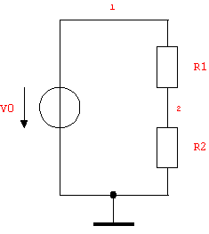
Figure 2.1: Voltage divider circuit
An Analog Insydes netlist desribing the circuit looks as follows:
In[1]:= <<AnalogInsydes`
In[2]:= voltageDivider =
Netlist[
{V0, {1, 0}, 10},
{R1, {1, 2}, R1},
{R2, {2, 0}, R2}
]
Out[2]= 
The Netlist command returns a raw netlist object which prints its content in short notation, i.e. only the number of elements is shown. To get a more detailed view of the netlist content use the command DisplayForm:
In[3]:= DisplayForm[voltageDivider]
Out[3]//DisplayForm= 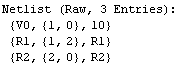
The netlist entry format (see Section 3.1.3) bears some remote similarity to that of the well-known and widely used numerical circuit simulator SPICE in that circuit elements are specified by an individual name, a list of nodes, and a value. In Analog Insydes, netlist entries must be lists of three fields which are called the reference designator, the connectivity list, and the value field:
 reference designator, reference designator,  connectivity list connectivity list , value field , value field
This global scheme describes the only valid syntax for netlist entries - there is no exception to this format.
Reference Designators
The reference designator is a unique name by which a particular circuit element can be distinguished from all other elements in the same netlist. Typically, the leading one, two, or three characters of a reference designator implicitly determine the type of the corresponding element. Hence, V0 denotes a voltage source (type tag V), R1 and R2 denote resistors (type tag R), and VCCS a voltage-controlled current source (type tag VC).
There are mechanisms to override automatic type detection from reference designators explicitly but this and other related advanced topics will be discussed later.
Unlike Mathematica variables, type tags are not case sensitive. Therefore, two circuit elements with reference designators R1 and r1 are both recognized as resistors. However, the symbols R1 and r1 represent two entirely different elements.
Connectivity Lists and Node Identifiers
The connectivity list specifies the nodes of the circuit to which the terminals of an element are connected. For that purpose, every node in a circuit must be given a unique name, a node identifier, by which it can be referenced. While some circuit simulators require the nodes to be enumerated by consecutive nonnegative integers, Analog Insydes lets you choose node identifiers quite freely. You do not have to number your nodes consecutively, nor do you need to use numbers as node identifiers at all. In addition to nonnegative integers, you may also use symbols or strings as node labels. The only requirement is that the circuit's ground node must be identified by the label 0 (zero). Internally all node identifiers are converted to strings. Thus, the node identifiers OUT and "OUT" refer to the same node. Moreover, node identifiers are case sensitive. Thus, OUT and Out refer to different nodes.
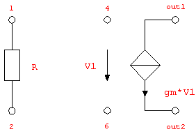
Figure 2.2: Resistor and voltage-controlled current source
For a two-terminal element, such as a resistor (Section 4.2.1), the connectivity list must contain exactly two node identifiers whereas a controlled source, i.e. a four-terminal element, requires four node identifiers: two for the controlling branch and two for the controlled branch. Netlist entries for the resistor and the voltage-controlled current source (Section 4.2.13) shown in Figure 2.2 thus have to be written as follows:
{R1, {1, 2}, R}
{VC2, {4, 6, out1, out2}, gm}
Reference Directions for Currents and Voltages
In Analog Insydes netlists, the order of the nodes in a connectivity list determines the positive reference direction for both the associated branch voltage and the branch current. In other words, the reference directions for voltages and currents always have the same orientation.
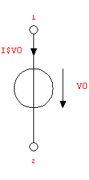
Figure 2.3: Voltage source, reference directions for branch voltage and current
In Figure 2.3, the positive terminal of the voltage source (Section 4.2.10) is connected to node 1, and the negative terminal is connected to node 2. The corresponding netlist entry then defines the positive reference direction for the branch voltage as well as for the current I$V0 to be oriented from node 1 to node 2:
{V0, {1, 2}, V0}
Hence, a positive value for the branch current,  , denotes a current flowing from node 1 to node 2. So whenever a circuit analysis yields a negative result for I$V0 there is nothing wrong. This just means that the current is in fact flowing into the opposite direction, i.e. from node 2 to node 1. , denotes a current flowing from node 1 to node 2. So whenever a circuit analysis yields a negative result for I$V0 there is nothing wrong. This just means that the current is in fact flowing into the opposite direction, i.e. from node 2 to node 1.
Element Values
As opposed to SPICE, the values of circuit elements need not be purely numerical quantities. Since Mathematica is capable of performing mathematical calculations symbolically, the element values may also be any symbolic or mixed symbolic/numeric expressions. In the voltage-divider example (see Figure 2.1) we assigned a numerical value of 10 (Volts) to the voltage source whereas we used the symbolic values R1 and R2 for the two resistors. (Note that you don't have to specify any units like Volts for numerical values.) In this case, the symbols used for the values of the resistors are identical to the reference designators, but we could also have supplied any other valid Mathematica expression.
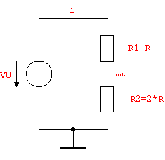
Figure 2.4: Voltage divider circuit with different node names and resistor values
Let's make use of some of the facts presented in the preceding paragraphs by renaming node 2 of the voltage divider to out, arbitrarily making the assignments  and and  , and rewriting the netlist accordingly (see Figure 2.4): , and rewriting the netlist accordingly (see Figure 2.4):
In[4]:= voltageDivider2 =
Netlist[
{V0, {1, 0}, 10},
{R1, {1, out}, R},
{R2, {out, 0}, 2 R}
]
Out[4]= 
|