|
2.2.2 Circuit Elements
Element Types
Having learned the basics about the netlist format we will now take a look at the circuit element types (see Chapter 4.2) which are supported by Analog Insydes. The names of all available types are stored in a globally accessible list named ElementTypes:
In[5]:= ElementTypes
Out[5]= 
To obtain information about the netlist format for a particular circuit element, type ?element. This will print the corresponding usage message to the screen. For example, let's find out more about the elements Capacitor and VCCSource:
In[6]:= ?Capacitor

In[7]:= ?VCCSource

You may have noticed that there are no such elements as diodes, bipolar or MOS transistors contained in ElementTypes.
Nevertheless, Analog Insydes comes with a predefined library of symbolic semiconductor device models (see Chapter 4.3), which contains full-precision SPICE-compatible models for the most important devices such as Diodes, BJTs, MOSFETs, and JFETs.
In addition to the linear electric circuit elements like resistors and capacitors the list of element types contains six elements from control theory, namely signal sources, amplifiers, integrators, etc. This is because Analog Insydes is capable of analyzing linear control circuits as well. You can even perform symbolic analyses of systems which contain both electrical and control components, allowing you to do behavioral circuit modeling across different levels of abstraction.
Controlled Sources: Some Caveats
If you have worked with SPICE netlists before you will see some differences in the way you have to formulate the netlist entries for controlled sources in an Analog Insydes netlist. Apart from the more meaningful type tags (VV, CC, VC, CV as opposed to E, F, G, H), Analog Insydes uses a uniform scheme for all four types of controlled sources, i.e. you have to specify two nodes for the controlling branch and two nodes for the controlled branch for both voltage-controlled and current-controlled sources.

Figure 2.5: Current-controlled voltage source (left) and voltage-controlled current source (right)
For the two controlled sources shown in Figure 2.5 the netlist entries must be written as follows. Note, that the nodes of the controlling branches are listed first.
{CV1, {C1, C2, N1, N2}, r}
{VC2, {1, 2, 3, 4}, gm}
Analog Insydes treats controlled sources as true two-port elements, so every controlled source adds two electrical branches to a circuit, a controlling and a controlled branch. In the case of current-controlled sources you have to keep in mind that the controlling branch is nothing else than a short circuit (Section 4.2.8). Therefore, do not connect the controlling branch of a current-controlled source in parallel to another circuit element. Instead, always use a series connection of the controlling branch and the circuit element whose branch current controls the source.
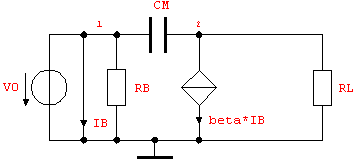
Let's clarify this important point by writing a netlist for the circuit shown in Figure 2.6. The current-controlled current source is controlled by the current flowing through the resistor RB. If we wrote the netlist entry for the CCCS (Section 4.2.11) as
{CC1, {1, 0, 2, 0}, beta}
the controlling branch would be inserted in parallel to RB and thus short-circuit the resistor.

Figure 2.6: Result of incorrectly inserted current-controlled current source
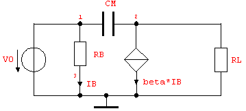
The correct solution to this problem is to add another node to the circuit and connect the controlling branch in series with RB as shown in Figure 2.7.

Figure 2.7: CCCS circuit with correctly inserted controlling branch
We can then write a correct netlist as follows:
In[8]:= cccsCircuit =
Netlist[
{V0, {1, 0}, V0},
{RB, {1, 3}, RB},
{CM, {1, 2}, CM},
{CC1, {3, 0, 2, 0}, beta},
{RL, {2, 0}, RL}
]
Out[8]= 
|