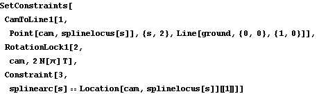
6.1.6 Rolling ContactIn order to have rolling contact between two cams, the arc length along the cam profile must be known as a function of the cam's controlling parameter. For cams that are built up from a sequence of piecewise continuous analytic functions, such as those shown in Section 6.1.1, it is often possible to build up a similar function that exactly represents the arc length of the cam. If a SplineFunction cam was used, the arc length cannot be explicitly stated, but Mech provides a function for approximating the arc length with another cubic spline. A spline utility. Example MechanismThe following example models a snail-shaped cam profile rolling on a stationary line. The cam is defined with a SplineFunction, and it is the single moving body in the mechanism. Note how the EndConditions option for SplineFit is used to specify the direction vector at the ends of the spline. Here are data points for a snail profile. SplineFit is applied to the data.
Out[39]= |  |
Here is a plot of the spline.
Out[40]= |  |
To constrain the snail-wheel to be in rolling contact, the arc length function of both contacting surfaces must be known. Since one of the two surfaces in this model is flat and has a trivial arc length function, only the arc length function of the snail-wheel must be determined. The Mech ArcLength function may work quite slowly, because it involves numerically integrating each segment of the SplineFunction object. Here is the arc length function of the snail spline.
Out[41]= |  |
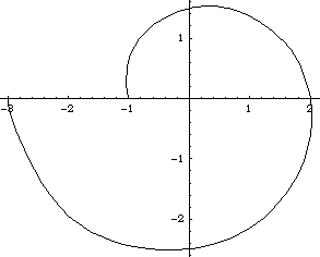
ConstraintsThe snail-wheel is modeled with just three constraints. A CamToLine1 constraint places the snail-wheel in contact with the surface of the ground. Note the initial guess for the cam parameter s that sets the initial contact point at the bottom of the cam.A RotationLock1 constraint controls the angular orientation of the snail-wheel.A Constraint sets the arc length along the snail-wheel equal to the arc length along the flat surface. The arc length along the flat surface is simply the X coordinate of the cam contact point.Names are defined for each body. Here are the snail-wheel constraints. Reasonable initial guesses are set for the snail-wheel. Now we run the model at three positions.
Out[46]= | 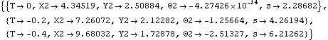 |
Snail-wheel graphic at each solution point.
Analytic Snail-WheelIn fact, this particular mechanism could have been modeled without the use of SplineFunction at all. The snail-wheel cam profile can be built from analytic functions and its arc length can be found using Mathematica's symbolic integration capability. Here is the definition of an analytic snail-wheel.
Out[47]= |  |
Here is the exact arc length function of the snail-wheel.
Out[48]= | 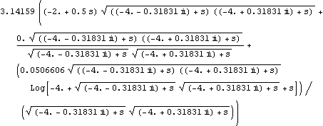 |
Here is a plot of the exact arc length function and the approximate arc length function, normalized to the same parameter scale and offset.
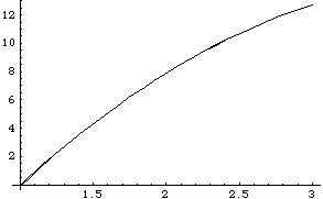
Out[49]= |  |
|