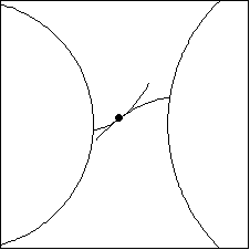
6.1.9 Involute GearsA single pair of involute gear teeth can be modeled with Modeler2D as a pair of cam surfaces. Modeler2D provides a function for generating the involute profiles based on the standard gear tooth specifications. The involute gear tooth function. An option for Involute. The following example uses two gear tooth loci (functions of the symbols g1 and g2) located on a pair of mating gears. Note that the coordinates of the center point and the rotation angle of the involute are given in local coordinates. The tooth loci are not placed onto their respective bodies until they are put into Modeler2D point objects. Here is a pair of tooth loci.
Out[60]= |  |
Four constraints are used to model the two gear teeth. A Revolute2 constraint forces the center of gear 1 to be located at {0, 0}. A RotationLock1 constraint rotates gear 1. A Revolute2 constraint forces the center of gear 2 to be located at {12, 0}. A CamToCam1 constraint is used to enforce the contact of the gear teeth.Here are the involute gear model constraints. The model is run at T = 0.01.
Out[65]= |  |
Here are the two gear teeth.

Note that the angular velocity ratio of the two gears is equal to the ratio of the radii of the base circles.
Out[66]= |  |
|