6.2 Gear ConstraintsMech provides several special constraint functions for modeling gear-type relationships. These constraints do not, in fact, model the interactions of the individual gear teeth. They simply enforce the nominal rotational relationship that is expected of a pair of gears. An example of involute gear tooth modeling can be found in Section 6.1. 6.2.1 2D Gear ConstraintsThe 2D gear constraints provided by Modeler2D cover three elementary cases of a gear-drive relationship. In each case, a simple rotational relationship is enforced between two bodies. Two gear constraints. Special gear constraints. Each gear constraint requires an initial position constant to set the initial relative rotational positions of the two gears. Physically, the constant C specifies which gear teeth are mating when the gears are first assembled, on a continuum.
The following TwoGears2 constraint would be used to model a pair of gears with pitch radii of 4.0 and 6.0, respectively, and local origins at {0, 0}. This method of setting the initial position constant causes the two gears to have angular coordinates of zero simultaneously, regardless of the relative positions of the centers of the gears.
Note that using Angle[gear1, 0, gear2, 0] in the orientation constant would produce invalid results if the centers of the gears were to move relative to each other, because the orientation constant is not constant. Here is an example of a gear constraint.
Out[4]= |  |
When an Euler solution method is used in a 2D model (Method -> Euler option for SetSymbols), an extra symbol must be added to the model to keep track of the gross rotations of each gear. This is because the degenerate Euler parameters can only uniquely represent rotations from 0 to 2 pi. The extra symbol can be generated automatically by SetConstraints, or it can be specified with an optional argument to each gear constraint.
These extra symbols, and their initial guesses, are analogous to the extra symbols introduced by all cam constraints and the Modeler2D gear constraints. Optional arguments for gear constraints with the Euler method. See the appendix for the optional arguments to other gear constraints. 6.2.2 Example 2D Gear MechanismTo demonstrate the use of Modeler2D gear constraints a 2D model is developed that uses a pair of gears, a pair of pulleys and a belt, and a rack and pinion. The input to the model is the specified rotation of the drive gear. This, in turn, rotates the driven gear, which is the same body as the drive pulley. The drive pulley rotates the driven pulley, which is the same body as the pinion. The rotation of the pinion causes the rack to translate. Here is a 2D gear-drive mechanism graphic.
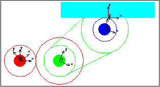
BodiesFive bodies are used in the gear-drive model. No body objects are defined because no explicit point coordinates are used in the model. Names are defined for each of the body numbers in the model. ConstraintsEight constraints are required to model the gear-drive mechanism. A Revolute2 constraint locates the center of the drive gear at the origin of the ground body.A RotationLock1 constraint controls the rotation of the drive gear.A TwoGears2 constraint controls the rotation of the drive pulley and specifies the distance between the drive gear and the drive pulley.A RelativeY1 constraint prevents the drive pulley from orbiting the drive gear.A TwoPulleys2 constraint controls the rotation of the pinion and specifies the distance between the drive pulley and the pinion.A RelativeY1 constraint prevents the pinion from orbiting the drive pulley.A RackAndPinion2 constraint controls the translation of the rack and specifies the orthogonal distance between the rack axis and the pinion center.A Parallel1 constraint forces the rack axis to be parallel to a horizontal line on the ground, which prevents the rack from orbiting the pinion. Here are the constraints for the gear model. RuntimeInitial guesses for the drive pulley, rack, and pinion must be set or the model will not converge. Almost any guesses greater than zero will do. This sets the initial guesses for the next solution attempt only.
Out[11]= |  |
Because of the presence of time T in the driving constraint, the model can be run through its intended range of motion by varying T directly with the SolveMech command. The numerical value of T specifies the angular coordinate of the drive gear. Now run the model at T = 0.05.
Out[12]= |  |
Now run the model at T = 0.25.
Out[13]= |  |
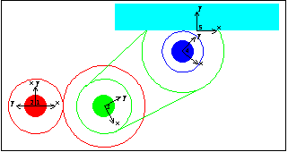
Here is the gear-drive mechanism at T = 0.25.
6.2.3 3D Gear ConstraintsThe 3D gear constraints provided by Modeler3D cover six elementary cases of a gear-drive relationship. In each case the gear constraints simply enforce a nominal rotational relationship between two bodies. The interactions of individual teeth on the gears are not modeled.
Each of the gear constraints must be passed an additional symbol alpha that is used by Modeler3D to keep track of the relative rotations of the gears. These symbols can be arbitrarily chosen, as long as all symbols in all gear constraints in a single model are unique. The values of these symbols are calculated by Modeler3D at runtime and included in the solution rules. Essentially, each new symbol is another dependent variable to be solved for, just like the coordinates of each body.
The numerical values of the added symbols correspond to the rotation of the first of the two gears in each pair, relative to the mutual orientation of the pair of gears in space. Two gear constraints. Each gear constraint requires an initial orientation constant to set the initial relative rotations of the two gears. In most simple gear trains the gears are initially aligned so the orientation constant can be zero.
The only significant differences between ParallelGears5 and TwoPulleys5 are that the separation distance of the two gears can be set independently from the gear radii with TwoPulleys5 and that the direction of relative rotation of the two gears is reversed. The direction of rotation constrained by TwoPulleys5 can be reversed by negating one of the two pulley radii. A special gear constraint. Another special gear constraint. As with TwoPulleys5, the direction of relative rotation specified by OrthogonalGears5 can be reversed by negating teeth1 or teeth2. A screw constraint. A constant velocity joint. Note that the ConstantVelocity4 constraint is not stable when the two axes are parallel. The included angle between the two axes must be kept sufficiently far from 0 or  to remain stable. If the two axes in a model need to be parallel or nearly so it may be useful to use the OrthoRevolute4 constraint instead. to remain stable. If the two axes in a model need to be parallel or nearly so it may be useful to use the OrthoRevolute4 constraint instead. The following ParallelGears5 constraint models a pair of gears with pitch radii of 4.0 and 6.0 respectively, and axis origins at local {0, 0, 0} on each body. The rotational axis of each gear is in its local z direction, and the local x direction on each gear is used as its reference direction. Setting the initial position constant to zero causes the reference directions of the two gears, the local x axes, and the vector from the center of gear1 to the center of gear2 to be simultaneously parallel. This loads the Modeler3D package. Here is a gear constraint example.
Out[17]= |  |
6.2.4 Example 3D Gear MechanismTo demonstrate the use of Modeler3D gear constraints a 3D model is developed that uses a pair of orthogonal bevel gears, a pair of parallel spur gears, and a rack and pinion gear set. The input to the model is the specified rotation of the first bevel gear, the drive bevel. This, in turn, rotates the driven bevel gear, which is the same body as the drive spur gear. The drive spur rotates the driven spur, which is the same body as the pinion. The rotation of the pinion causes the rack to translate. Here is the 3D gear-drive mechanism.
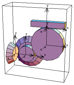
BodiesFive bodies are used in the gear-drive model. No body objects are defined because no explicit point coordinates are used in the model. Names are defined for each of the body numbers in the model. ConstraintsEight constraints are required to model the gear-drive mechanism. A Revolute5 constraint controls the rotational axis of the drive bevel. The drive bevel rotates about an axis originating at the global origin and pointing in the global X direction, which is coincident with the drive bevel's local x axis.A ProjectedAngle1 constraint specifies the rotation of the drive bevel.An OrthogonalGears5 constraint enforces the gear relationship between the drive bevel and the driven bevel (drive spur). The Axis objects that are used to specify the axes of each gear contain several important elements. The origins of the two axes are to be adjacent, thus they are located on the gear axes at the intended point of intersection of the axes. The local coordinate axes of the drive spur are initially rotationally aligned with the local axes of the drive bevel. Thus, the reference direction of each gear is initially parallel to the rotational axis of its neighbor, which results in an orientation constant of zero. Note also that these are straight cut bevel gears, so the offset distance between their axes is also zero.A RelativeY1 constraint removes the one remaining degree of freedom from the drive spur, its freedom to orbit drive bevel.A ParallelGears5 constraint enforces the gear relationship between the drive spur and the driven spur (pinion). The rotational axes of these two gears are to be parallel, so they both point in the local z direction. The orientation constant allows the two gears to be initially aligned with the global axes.A RelativeY1 constraint prevents the pinion from orbiting the drive spur.A RackAndPinion5 constraint controls the translation of the rack and the orthogonal distance between the rack axis and the pinion center. The radius of the rack is specified as - 3.0 to put the pinion on the correct side of the rack for this model.A Orthogonal1 constraint prevents the rack from orbiting the pinion.Here is the complete constraint set for the gear-drive model. RuntimeInitial guesses for the rack and pinion must be set or the model will not converge. This sets the necessary initial guesses. Because of the presence of T in the driving constraint, the model can be run through its intended range of motion by varying T directly with the SolveMech command. The numerical value of T specifies the angular coordinate of the drive bevel. Now run the model at T = 0.05.
Out[26]= |  |
Now run the model at T = 0.25.
Out[27]= |  |
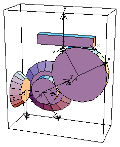
Here is the gear-drive mechanism at T = 0.25.
From the sizes of the gears in this model and the fact that the drive bevel is turning at one revolution per second, we can calculate what the velocity of the rack should be. This can also be found directly from the velocity of the rack in the Modeler3D model.

Here is the rack velocity, calculated explicitly and from the model.
Out[28]= |  |
Out[29]= |  |
6.2.5 General Rotational RelationshipsIf the spatial gear constraints provided by Modeler3D will not serve to model a more abstract rotational relationship, similar constraints can be built up from the basic kinematic constraints. The following example shows how to duplicate the function of the ParallelGears5 constraint with a set of other Modeler3D constraints.
This model consists of one moving body, the gear, and one stationary body, the pinion. The radius 3.0 gear orbits the stationary radius 1.0 pinion. The ParallelGears5 constraint is effectively replaced by the set of the following six constraints. A Parallel2 constraint forces the axes of the two gears to be parallel.A PointOnPlane1 constraint forces the origins of the two gear axes to be adjacent.A RelativeDistance1 constraint holds the gears the correct distance apart.A ProjectedAngle1 constraint sets the relative rotation of the pinion equal to the value of an extra symbol that is added to the model.A ProjectedAngle1 constraint sets the relative rotation of the gear equal to another extra symbol that is added to the model.A general Constraint object relates the two extra symbols that control the relative rotation of the two gears to each other.This combination constrains seven degrees of freedom, but it adds two degrees of freedom by adding two variables to the model. Thus, a total of five degrees of freedom are constrained. Here are names for the body numbers. Here is the equivalent ParallelGears5 constraint. We define a driving constraint to move the gear vertically so as to orbit the pinion. SetConstraints must be passed a flat constraint list. One initial guess is needed. Now run the model at T = 1.0.
Out[36]= |  |
Here is the two-gear model at T = 1.0.
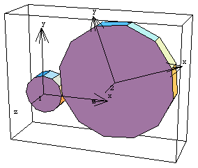
In general, this method of constraining the relative rotation between two moving bodies can be used to model any type of rotational linkage. The Constraint function that is used to relate the two extra variables can contain an algebraic expression that is arbitrarily complex. This allows abstract or nonlinear relationships to be modeled. Undocumented Graphics GenerationThe following inputs generate the graphics in this section. These Modeler2D and Modeler3D commands are defined in Chapter 3. 2D Gear Drive Mechanism3D Gear Drive MechanismGeneral Gear
|