|
Cable Pendulum Example Mechanism for Modeler3Dby Robert Beretta

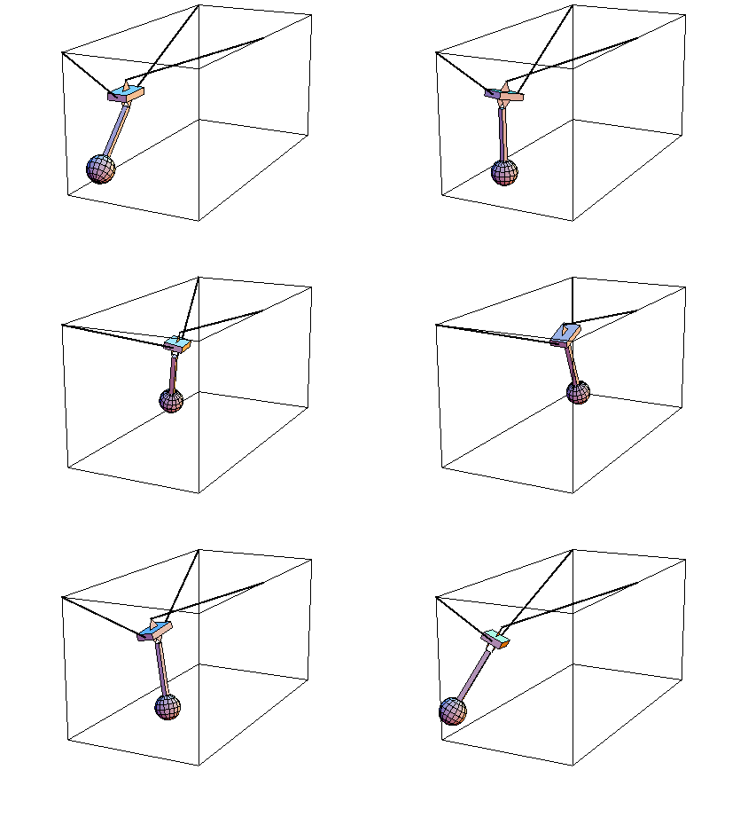
Cable Pendulum AnimationDiscussionThis sample notebook uses MechanicalSystems to analyze the dynamic motion of a 3D cable pendulum. The model consists of three bodies--the ground, the block, and the pendulum.
The pendulum is attached to the block by a revolute joint, or hinge. This joint allows one degree of dynamic freedom between the block and the pendulum.
The block is attached to the ground by two cables. One cable is fixed to a point on the ground and a point on the block, effectively forcing the point on the block to lie on a spherical surface in inertial space. The other cable is attached to two points on the ground and passes frictionlessly through a hole in the block. This effectively forces a point on the block to lie approximately on the surface of an ellipse in inertial space. The combination of the two cables constrains two degrees of freedom, leaving the block four degrees of dynamic freedom.
Because of the offset attachment points of the two cables on the block, the five degrees of dynamic freedom of the cable pendulum are highly coupled, and the free response of the system is rather complex. Kinematic ModelPreparationThe Modeler3D package is loaded with the Needs command. Names are defined to reference each of the bodies in the model, and the X, Y, and Z unit vectors are named for convenience. BodiesNo local point definitions are made in this model, so the only need for body objects is to define the inertia properties of the block and the pendulum. The pendulum is assumed to be a point mass, thus its moments and products of inertia are zero. ConstraintsA total of eight constraint objects are used in the cable pendulum model, but three of them are present only so that the model can be fully constrained and assembled prior to doing the dynamic simulation. These constraints will be dropped for the simulation. The remaining five constraint objects represent the two cables and the revolute joint.
1. The revolute joint between the block and the pendulum is modeled by a Revolute5 constraint, which constrains five degrees of freedom. 2. The first cable, which is attached solidly to the ground and the block, is modeled by a RelativeDistance1 constraint. 3, 4, and 5. The second cable, which is allowed to slide through a hole in the block, is modeled by two RelativeDistance1 constraints. Each constraint represents one side of the cable, but the length of each side is equal to a constant length 8 minus the length of the other side. A new dependent variable s is added to the model to represent the length of one side of the cable, thus, the length of the other side is 8 - s. The variable s is added to the model with Constraint, with an empty list as its equation argument. Thus, the combination of these three constraints removes two degrees of freedom, but adds one new one for a net constraint of one degree of freedom. 6 and 7. A RotationLock3 constraint and a RelativeX1 constraint are used to temporarily constrain the rotation and translation of the block. These constraints are used to set up the initial configuration of the model to prepare it for simulation, at which time they will be dropped to give the block dynamic freedom. 8. A RelativeAngle1 constraint is used to initially lock the revolute joint. This constraint will also be dropped for the dynamic simulation. LoadsLoads must be applied to the model (or nonzero initial velocity conditions) or its response will not be very interesting. A simple gravitational load is applied to the block and the pendulum. RuntimeThe kinematic model is now complete. The parameters must be defined before the model can be run. The initial guesses need to be pushed a little closer to reality than {0, 0, 0, 0, ...} or the model cannot converge. SolveMech is run to bring the model to the initial configuration that will be used as the initial condition for the dynamic simulation. The Solution -> Kinematic option is used to cause SolveMech calculates the values of the Lagrange multipliers so that some reaction forces can be examined, and to calculate velocities so they will be available as initial conditions. The velocities are all zero because the model has no explicit time dependence. If initial velocities were not available for the dynamic simulation, zero velocities would be assumed anyway.
A time specification, 0, is given to SolveMech to make an initial time available for the dynamic simulation. The initial time would also be assumed to be zero if none was available. Here is the reaction that constraint 3 applies to the coordinate s; the tension in the sliding cable. GraphicsHere is a graphic of the cable pendulum model in its initial configuration. Here is an image of the cable pendulum in its initial configuration.

DynamicsSetFree is used to create a new set of equations of motion with constraints 6, 7, and 8 dropped. The new equations are contained in the FreeSystem object, which is solved with SolveFree. SolveFree integrates the equations of motion from the initial time, which was pulled from the last available solution rule along with the other initial conditions, to the specified final time 5.0. The MakeRules option causes the generalized forces and the location coordinates to be returned by SolveFree so that reaction forces can be plotted. Here is a plot of the sliding cable parameter s.

Here is a plot of the tension in the cable.

The following input will generate a sequence of 20 graphics that can be animated to show the dynamic response of the model. End
|