11.3.2 Four-Bar ExampleAnother useful manipulation of the mass matrix is to find a minimal mass matrix for a model with a nonminimal coordinate system. While this can theoretically be done with or without generalized coordinates, it often becomes intractable when modeling in Cartesian coordinates because of the need to invert a large symbolic matrix.
The four-bar model that was developed previously in this section is used again here to demonstrate the formulation of a minimal mass matrix. In this case, the minimal mass matrix is a  matrix because the four-bar model has only one degree of freedom. Since the four-bar mechanism is modeled with three generalized coordinates alpha, beta, and gamma, the default mass matrix generated by Mech is a matrix because the four-bar model has only one degree of freedom. Since the four-bar mechanism is modeled with three generalized coordinates alpha, beta, and gamma, the default mass matrix generated by Mech is a  matrix; the task at hand is to reduce it to matrix; the task at hand is to reduce it to  . Note that inertia properties are included in the body objects of this version of the four-bar. . Note that inertia properties are included in the body objects of this version of the four-bar. This clears all data in the current Mech model. Bodies and ConstraintsThe entire four-bar model is redefined without explanation here, because its kinematics are completely documented in Section 8.3.2. Here are the body objects for the four-bar model. Here are the generalized coordinate constraint objects. Mass MatrixWe intend to transform the  system mass matrix M into a system mass matrix M into a  mass matrix m where mass matrix m where  and f is the generalized force in the direction of alpha, which is simply a counterclockwise moment applied to the drive bar. This transformation is of the form and f is the generalized force in the direction of alpha, which is simply a counterclockwise moment applied to the drive bar. This transformation is of the form  . .
The necessary transformation matrix J converts motions in all three generalized coordinates into motions of the single coordinate alpha. This matrix J is created by inverting the part of the model's Jacobian associated with beta and gamma and multiplying it by the part associated with alpha. The resulting 2x1 matrix converts alpha only into beta and gamma, so it must be prepended with a 1 to convert alpha into all three coordinates.
Only the part of the Jacobian associated with constraint 5 is included in the calculation because the driving constraint (constraint 1) must be dropped for the model to have more than zero degrees of freedom, and the other three generalized coordinate constraints contribute no constraint equations. Here is the  transformation matrix J. transformation matrix J. Here is the  system mass matrix. system mass matrix.
Out[28]= |  |
Here is the  mass matrix in terms of the coordinate alpha. mass matrix in terms of the coordinate alpha. Since m is a  matrix it may as well be a scalar, and the acceleration that results from applying a moment to the drive bar is simply matrix it may as well be a scalar, and the acceleration that results from applying a moment to the drive bar is simply  . Remember that m is still a function of alpha, beta, and gamma, and not just any set of alpha, beta and gamma will do (unlike the two-link manipulator in which any values of the coordinates could be specified). SolveMech must be used to find a set of coordinates that represents a valid configuration of the four-bar model. . Remember that m is still a function of alpha, beta, and gamma, and not just any set of alpha, beta and gamma will do (unlike the two-link manipulator in which any values of the coordinates could be specified). SolveMech must be used to find a set of coordinates that represents a valid configuration of the four-bar model. The  matrix m is converted to a scalar. matrix m is converted to a scalar. Here is the configuration of the four-bar model at 1/8 turn of the drive bar.
Out[31]= |  |
Here is the acceleration that results from a 10-unit moment applied to the drive bar.
Out[32]= |  |
Dynamic MotionThe constrained dynamic motion profile of the four-bar model can be found with the SetFree and SolveFree functions, as described in Chapter 10. In this example, the drive bar is given an initial angular velocity of 2 pi radians/second, a condition that is inherent in the definition of constraint 1. Constraint 1 is dropped from the model, and the free motion of the underconstrained system is found. The model is run at T = 0 to make initial conditions available to SetFree. Here is the FreeSystem object that contains the dynamical equations of motion, with constraint 1 dropped.
Out[34]= |  |
The FreeSystem object fsys is integrated in the time domain from T = 0.0 to 2.0 with SolveFree. All initial conditions for the integration are taken from the most recent solution returned by SolveMech. Here is the time domain solution.
Out[35]= |  |
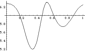
Here is a plot of the angular velocity of the drive bar through approximately one full revolution of the drive bar.

Out[36]= |  |
|