3.1.1 Example Mechanism To demonstrate the use of Modeler2D output functions, a 2D model is developed that can have various geometric quantities measured. The model is a planar quick-return mechanism consisting of three moving bodies: the crank, drive arm, and slider. A real quick-return mechanism would have a fourth body, the connecting rod between the drive arm and the slider, but this body is simply modeled with a relative-distance constraint.
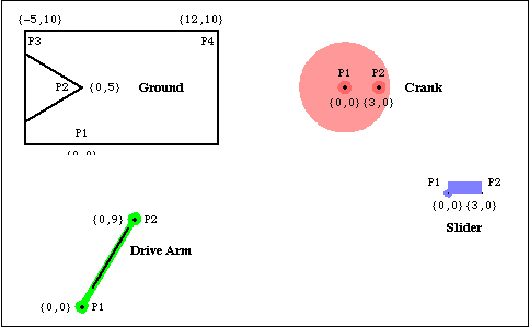
The motion of the quick-return mechanism is driven by the rotation of the crank that, in turn, forces the drive arm to rock about its lower pivot point on the ground, via a pin on the crank that slides in a straight slot on the drive arm. The top of the drive arm is attached to a connecting rod, which is attached to the slider, which slides on horizontal path on the ground. This loads the Modeler2D package. Here is a graphic of the 2D quick-return model.

BodiesFour body objects are defined for the quick-return mechanism model. The ground (body 1) requires four point definitions.
P1 is the rotational axis of the drive arm.
P2 is the rotational axis of the crank.
P3 and P4 are two points that define the line upon which the slider slides.The crank (body 2) requires two local point definitions.
P1 is the crank's rotational axis.
P2 is the location of the pin on the crank that engages with the drive arm.The drive arm (body 3) requires two local point definitions.
P1 is the point on the drive arm where the drive arm pivots with respect to the ground.
P2 is the point where the drive arm is attached to the pseudo-connecting rod.The slider (body 4) requires two local point definitions.
P1 and P2 are two points along the horizontal axis of the slider define its translation line.Here are the bodies in the quick-return model.

Names are defined for each of the body numbers in the mechanism. Body objects are defined for each body. This incorporates the body properties into the current model. ConstraintsFive constraints and one driving constraint are required to model the quick-return mechanism. A Revolute2 constraint forces the axis of the crank to be coincident with its pivot point on the ground. This constrains two degrees of freedom, X and Y displacement of the crank axis.A RotationLock1 constraint specifies the angular coordinate of the crank. This driving constraint is used to rotate the crank.A Revolute2 constraint forces the lower pivot point of the drive arm to be coincident with the global origin. The drive arm can pivot about this point on the ground.A PointOnLine1 constraint between the crank and the drive arm where the pin on the crank slides in a slot on the drive arm.A RelativeDistance1 constraint between the drive arm and the slider replaces the pseudo-connecting rod, which is 5.0 units long.A Translate2 constraint between the slider and the ground allows the slider to translate horizontally along a track on the ground.Here are five constraints for the quick-return model. This incorporates the constraints into the current model. RuntimeThis runs the model at T = 0.15
Out[18]= |  |
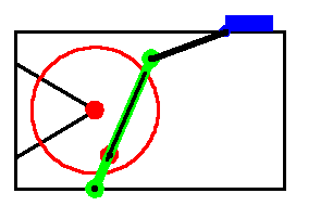
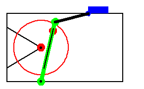
Here is the quick-return mechanism at T = 0.15.

|