Slider-Crank Mechanism
Slider-Crank Mechanism
Model the motion of a simple slider-crank mechanism subject to an external force.
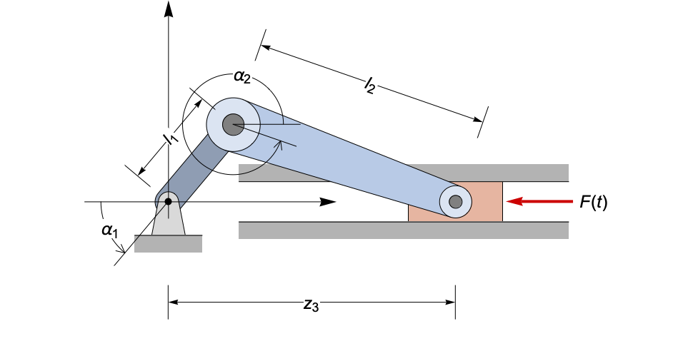
The state of the slider-crank mechanism can be described completely by two angles  ,
,  and the distance
  of the slider from origin:
vars = {α1, α2, z, λ1, λ2};F[t] := -1;The equations of motion are derived by resolving the forces and applying Newton's law  and
and  . The crank and connecting rod have mass and therefore inertia:
s1 = Sin[α1[t] - α2[t]];
c1 = Cos[α1[t] - α2[t]];
LM = (L1 L2 m2) / 2;
eqns = {(J1 + m2 L1^2) α1''[t] + LM c1 α2''[t] == -LM s1 α2'[t]
	 - (L1 Cos[α1[t]] λ1[t] + L1 Sin[α1[t]] λ2[t]),
	LM c1 α1''[t] + J2 α2''[t] == LM s1 α1'[t]^2
	 - (L2 Cos[α2[t]] λ1[t] + L2 Sin[α2[t]] λ2[t]),
m3 z''[t] == -F[t] - λ2[t]};constraints = (| |
| ---------------------------------------- |
| L1 Sin[α1[t]] + L2 Sin[α2[t]] == 0 |
| z[t] - L1 Cos[α1[t]] - L2 Cos[α2[t]] == 0 |);params = {J1 -> 4.5, J2 -> 5.5, m1 -> 1, m2 -> 1, m3 -> 1, L1 -> 1, L2 -> 2, g -> 9.81};{sliderCrank} = NDSolve[{eqns, constraints, α1[0] == Pi / 4, α1'[0] == -1} /. params, vars, {t, 0, 20}, Method -> {"IndexReduction" -> Automatic}];Plot[Evaluate[{λ1[t], λ2[t]} /. sliderCrank], {t, 0, 10}, PlotStyle -> {Red, Blue},
PlotLegends -> Placed[LineLegend[{Red, Blue}, {"Tension in Crank (λ1)", "Tension in Connecting Rod (λ2)"}], Bottom], ImageSize -> 300]