WOLFRAM SYSTEM MODELER
BaseParallelRLCPartial model of a parallel RLC circuit |
|
Diagram
Wolfram Language

SystemModel["DocumentationExamples.Modeling.ElectricCircuit.BaseModels.BaseParallelRLC"]

Information
Wolfram Language Documentation Examples
This library contains models used in the documentation of system modeling functionality in Wolfram Language. These examples and this library can be explored in the Wolfram Language documentation.
Parameters (3)
| r |
Value: 137.046 Type: Resistance (Ω) Description: Resistance at temperature T_ref (rs.R) |
|---|---|
| l |
Value: 0.12696 Type: Inductance (H) Description: Inductance (ls.L) |
| c |
Value: 1.194e-05 Type: Capacitance (F) Description: Capacitance (cs.C) |
Connectors (1)
| vo |
Type: RealOutput Description: 'output Real' as connector |
|---|
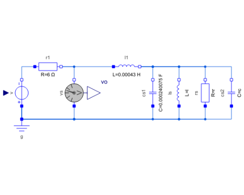
Components (9)
| r1 |
Type: Resistor Description: Ideal linear electrical resistor |
|
|---|---|---|
| g |
Type: Ground Description: Ground node |
|
| rs |
Type: Resistor Description: Ideal linear electrical resistor |
|
| ls |
Type: Inductor Description: Ideal linear electrical inductor |
|
| cs2 |
Type: Capacitor Description: Ideal linear electrical capacitor |
|
| v |
Type: SignalVoltage Description: Generic voltage source using the input signal as source voltage |
|
| vs |
Type: VoltageSensor Description: Sensor to measure the voltage between two pins |
|
| cs1 |
Type: Capacitor Description: Ideal linear electrical capacitor |
|
| l1 |
Type: Inductor Description: Ideal linear electrical inductor |
Extended by (2)
|
DocumentationExamples.Modeling.ElectricCircuit RLC circuit with real input for voltage source |
|
|
DocumentationExamples.Modeling.ElectricCircuit RLC circuit with sine voltage source |

