WOLFRAM SYSTEM MODELER
BuckConverterBuck converter and Zener regulator comparison. |
|
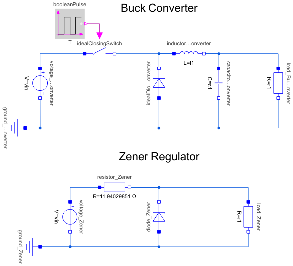
Diagram
Wolfram Language
In[1]:=
SystemModel["EducationExamples.ElectricalEngineering.BuckConverter"]
Out[1]:=
Information
Using a linear DC‐to‐DC regulator is one of the simplest ways to reduce the voltage of a DC supply. However, as linear regulators work by converting excess power to heat, they are highly inefficient and inconvenient to use in many applications. A common alternative to reduce DC voltage is instead to use a buck converter. In this example, we study the difference in efficiency between a buck converter and a simple (linear) Zener regulator when converting a supply voltage of 24 V to an output voltage of 12 V.
Dynamics
A buck converter is a switched-mode power supply that uses a switch, a diode, an inductor, and a capacitor to convert direct current voltage from a higher to a lower level. When the switch is turned off, the inductor current freewheels through the diode. When the switch is turned on, the inductor current increases and doesn’t pass through the diode.
Simulation
To simulate the model, click the Simulate button in the top toolbar: 
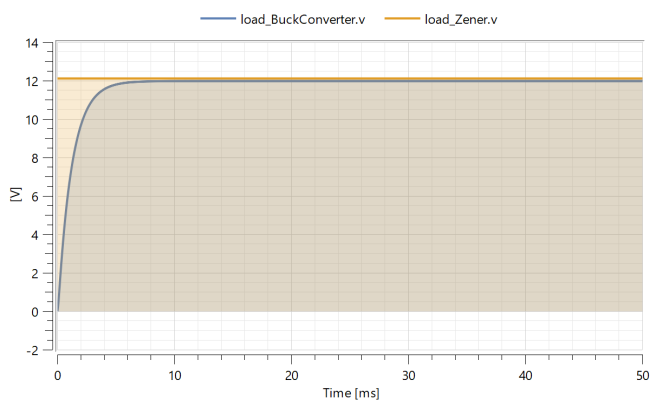
Plot the results
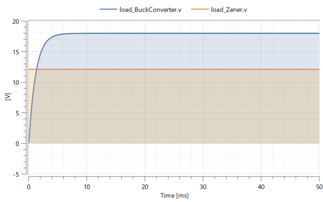
When the simulation is done, a Model plot will automatically be displayed:
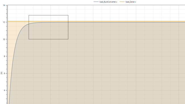
Zoom
The switch is continuously being opened and closed by the boolean pulse supplied to it. This happens so fast that it is hard to discern from the graph.
Zoom in on the graph to explore the ripple caused by the buck converter. To do this, perform the following steps
- In the Plot Window, position your mouse cursor around 13 V on the Y-axis and 0.009 s.
- Draw a small box around the plots (see picture) by clicking and dragging your mouse cursor. When you release the button, you will zoom in on the selected area
- To return to the original view, right click anywhere in the Plot Window and select Rescale.
Change Parameters
Changing parameters for the simulation can be done rapidly in Simulation Center. The D parameter determines the duty-ration of the buck converter. This is determined by the relative duration between the closed/on period and the open/off period. The standard value for this parameter is 0.5 which means that 50% of the time, the switch will be closed and the voltage source will be connected to the circuit. The resulting voltage over the load will be 50% of the input voltage.
Try changing the duty-ration of the converter, D and see how this affects the controller:
- Switch to the Parameter tab to the left in the Experiment Browser.
- Scroll down to the D parameter and change its value to 0.75 by typing into the box to the right of the parameter.
- Simulate again by following the steps in the Simulation section to see the effects of your changes.
You should now see the graph below, note that the Zener regulator is not affected by the parameter change above:
Parameters (6)
| r1 |
Value: 16 Type: Resistance (Ω) Description: Resistance for the load |
|---|---|
| c1 |
Value: 4e-006 Type: Capacitance (F) Description: Capacitance of the buck converter capacitor |
| l1 |
Value: 0.02 Type: Inductance (H) Description: Inductance of the buck converter inductor |
| T |
Value: 5e-005 Type: Time (s) Description: Time for one period |
| D |
Value: 12 / 24 Type: Real Description: Duty-ratio |
| vin |
Value: 24 Type: Voltage (V) Description: Input voltage into the buck converter |
Components (13)
| voltage_BuckConverter |
Type: ConstantVoltage Description: Source for constant voltage |
|
|---|---|---|
| load_BuckConverter |
Type: Resistor Description: Ideal linear electrical resistor |
|
| capacitor_BuckConverter |
Type: Capacitor Description: Ideal linear electrical capacitor |
|
| inductor_BuckConverter |
Type: Inductor Description: Ideal linear electrical inductor |
|
| ground_BuckConverter |
Type: Ground Description: Ground node |
|
| booleanPulse |
Type: BooleanPulse Description: Generate pulse signal of type Boolean |
|
| idealDiode_BuckConverter |
Type: IdealDiode Description: Ideal diode |
|
| idealClosingSwitch |
Type: IdealClosingSwitch Description: Ideal electrical closer |
|
| voltage_Zener |
Type: ConstantVoltage Description: Source for constant voltage |
|
| load_Zener |
Type: Resistor Description: Load attached to the circuit |
|
| ground_Zener |
Type: Ground Description: Ground node |
|
| resistor_Zener |
Type: Resistor Description: Ideal linear electrical resistor |
|
| diode_Zener |
Type: ZDiode Description: Zener diode with 3 working areas |