WOLFRAM SYSTEM MODELER
DCMotorA simple model of a DC motor. |
|
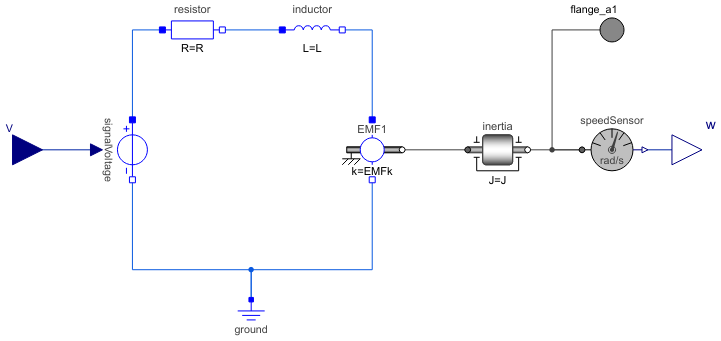
Diagram
Wolfram Language
In[1]:=
SystemModel["EducationExamples.ElectricalEngineering.DCMotor.Components.DCMotor"]
Out[1]:=
Information
A simple dynamic model of a controlled DC motor consisting of a variable voltage source, a resistor, an inductor, and an electro-motoric force element representing the coupling between electric energy and mechanical energy provided by the magnetic field in the DC motor. The motor axis is represented by a rotating inertia.
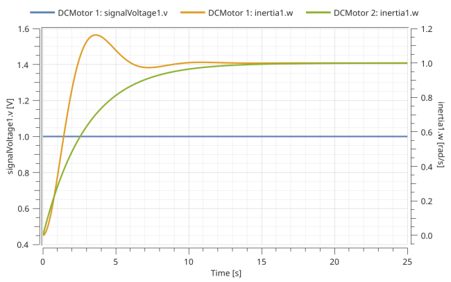
Comparison of step response for the rotational speed of the inertia using the default parameters (DCMotor 1) and with resistance set to 10 Ohm, inductance 0.1 H, and moment of inertia to 0.3 kg m2 (DCMotor 2):
For a step by step tutorial see Multidomain—A Servo Mechanism.
Parameters (4)
| R |
Value: 13 Type: Real |
|---|---|
| L |
Value: 1 Type: Real |
| J |
Value: 1 Type: Real |
| EMFk |
Value: 1.6 Type: Real |
Connectors (3)
| w |
Type: RealOutput Description: 'output Real' as connector |
|
|---|---|---|
| V |
Type: RealInput Description: 'input Real' as connector |
|
| flange_a1 |
Type: Flange_a Description: One-dimensional rotational flange of a shaft (filled circle icon) |
Components (7)
| resistor |
Type: Resistor Description: Ideal linear electrical resistor |
|
|---|---|---|
| inductor |
Type: Inductor Description: Ideal linear electrical inductor |
|
| EMF1 |
Type: RotationalEMF Description: Electromotoric force (electric/mechanic transformer) |
|
| ground |
Type: Ground Description: Ground node |
|
| signalVoltage |
Type: SignalVoltage Description: Generic voltage source using the input signal as source voltage |
|
| speedSensor |
Type: SpeedSensor Description: Ideal sensor to measure the absolute angular velocity of flange |
|
| inertia |
Type: Inertia Description: 1D-rotational component with inertia |
Used in Examples (2)
|
EducationExamples.ElectricalEngineering.DCMotor.Components Component that can be interacted with through Mathematica. |
|
|
EducationExamples.ElectricalEngineering.DCMotor DCMotor that is controlled by a unit step. |