WOLFRAM SYSTEM MODELER
RectifierRectifier that transforms and converts AC current to DC current. |
|
Diagram
Wolfram Language
In[1]:=
SystemModel["IndustryExamples.Other.Rectifier"]
Out[1]:=
Information
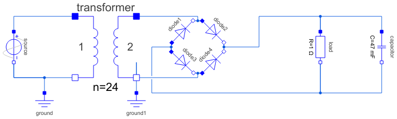
This model studies the full-wave bridge rectifier. A rectifier is a circuit in which alternating current (AC), such as the one coming from ordinary household power sockets, is converted into direct current (DC). Direct current is needed for low-voltage appliances such as computer circuitry.
Model Principles
The model uses an AC input voltage of 230 V with a frequency of 60 Hz. Through the use of an ideal transformer, the voltage is transformed down to around 9.5 V. The other end of the transformer is connected to four diodes. The diodes will only let current pass through in one direction, which is indicated by the arrow in the diode icon. Additionally, the voltage over the diode will also need to be higher than the diode forward voltage threshold. For silicon diodes, this voltage threshold is around 0.6 to 0.7 volts.
When the voltage source produces a positive potential on the positive pin, the current will pass through two of the diodes, one on the way into the load and one on the way back from the load. When the polarity of the voltage source is reversed, the two diodes that previously let current through in their forward direction will now block current in their backward direction, and the current will flow through the two remaining diodes. Regardless of polarity, the current will enter the load through the positive pin (filled, blue).
With only the transformer, the rectifier, and the load, the voltage over the load will alternate from zero to positive peak voltage. To reduce the ripple over the load, one or more capacitors are often added. The capacitor will oppose the change in voltage. It will store energy during the peak periods and release energy during the off periods. The capacitance of the capacitor needed depends on the amplitude of the AC voltage. For this low-voltage circuit (~10 V), a 47 mF capacitor is used.
Simulation
To simulate the model, click the Simulate button: 
Plot the Results
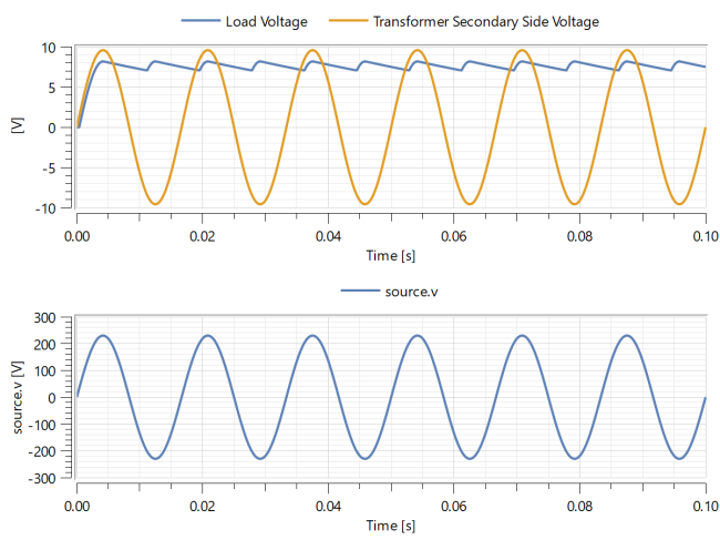
Examine the automatically displayed stored plot and see how the alternating current gets converted to direct current. Explore how the voltage from the transformer (before rectification) compares to the voltage over the load (after rectification).
You can also compare the rectified voltage to the voltage before transformation. The source voltage is higher than the transformed voltage by a factor of 24.
You should now see the following graphs:
Analysis
Study the graphs produced in the Simulation section. Notice how the load voltage never reaches the transformer peak voltage. Regardless of voltage, it will always deviate 1.4 V from the peak. This is due to voltage drop caused by the silicon diodes.
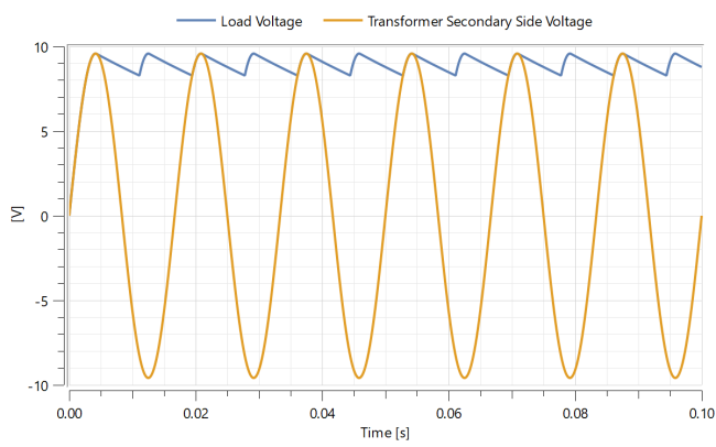
You can verfy that this is the case by changing the forward voltage of the diodes. Do this by performing the following steps:
- Switch to the Parameter tab on the left in the Experiment Browser.
- Scroll down to the Vforward parameter. This is the parameter that describes the minimum voltage needed to get current flowing in the diodes' forward direction.
- Change the value of the Vforward parameter to 0 by typing 0 in the box next to the parameter.
- Simulate by clicking the Simulate button or by pressing Ctrl+R.
Now that 0 voltage is needed for the current to flow through in the forward direction, the peak voltage from the transformer should be equal to the peak voltage over the load.
You should now see the graph below:
Parameters (1)
| Vforward |
Value: 0.7 Type: Voltage (V) Description: Forward voltage drop of diodes |
|---|
Components (10)
| diode1 |
Type: IdealDiode Description: Forward-biased diode to rectify current |
|
|---|---|---|
| diode3 |
Type: IdealDiode Description: Forward-biased diode to rectify current |
|
| diode4 |
Type: IdealDiode Description: Forward-biased diode to rectify current |
|
| diode2 |
Type: IdealDiode Description: Forward-biased diode to rectify current |
|
| load |
Type: Resistor Description: Resistive component to simulate a resistive load |
|
| capacitor |
Type: Capacitor Description: Smoothing capacitor |
|
| source |
Type: SineVoltage Description: Mains electricity |
|
| transformer |
Type: IdealTransformer Description: Transformer converting mains electricity to lower voltage |
|
| ground |
Type: Ground Description: Mains neutral |
|
| ground1 |
Type: Ground Description: Mains neutral |