WOLFRAM SYSTEM MODELER
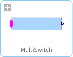
MultiSwitchSet Real expression that is associated with the first active input signal |
|
Wolfram Language
SystemModel["Modelica.Blocks.Math.MultiSwitch"]

Information
This information is part of the Modelica Standard Library maintained by the Modelica Association.
This block has a vector of Boolean input signals u[nu] and a vector of (time varying) Real expressions expr[nu]. The output signal y is set to expr[i], if i is the first element in the input vector u that is true. If all input signals are false, y is set to parameter "y_default".
// Conceptual equation (not valid Modelica)
i = 'first element of u[:] that is true';
y = if i==0 then y_default else expr[i];
The input connector is a vector of Boolean input signals. When a connection line is drawn, the dimension of the input vector is enlarged by one and the connection is automatically connected to this new free index (thanks to the connectorSizing annotation).
The usage is demonstrated, e.g., in example Modelica.Blocks.Examples.RealNetwork1.
Parameters (3)
| y_default |
Value: 0.0 Type: Real Description: Default value of output y if all u[i] = false |
|---|---|
| nu |
Value: 0 Type: Integer Description: Number of input connections |
| precision |
Value: 3 Type: Integer Description: Number of significant digits to be shown in dynamic diagram layer for y |
Inputs (1)
| expr |
Default Value: fill(0.0, nu) Type: Real[nu] Description: y = if u[i] then expr[i] else y_default (time varying) |
|---|
Connectors (2)
| u |
Type: BooleanVectorInput[nu] Description: Set y = expr[i], if u[i] = true |
|
|---|---|---|
| y |
Type: RealOutput Description: Output depending on expression |
Used in Examples (1)
|
Modelica.Blocks.Examples Demonstrates the usage of blocks from Modelica.Blocks.Math |
